Presented here are more tips and tricks for proper planning when CNC machining:
- One of the first and simplest things to look for when performing operations that involve vises is the length of the contact area between the part and the vise jaws. In general, choose the longest contact area possible. Figure 1a shows a setup made as rigid as possible before any material is removed. Initially, aggressive cuts can be made with high feed rates to remove material. As the “window” cut (Figure 1b) nears completion, the part becomes much weaker, and lighter cuts must be taken. These types of machining scenarios are common and must be planned in advance.
- Rigidity is important. As you envision or simulate material being cut away, think about the rigidity of the part and setups. When possible, choose a sequence where you can apply short, sturdy endmills. Long endmills are sensitive and less forgiving of higher feeds and speeds than short ones. They usually need to be run slower. Long endmills have a tendency to chatter and push away. If you need to apply long tools to cut tall or deep features, sequence the setups so that the long endmills are run when the workpiece has the most rigidity. If you use long endmills on a part that has already been weakened by previous machining, you’ll likely compound difficulties.
- Planning begins by visualizing the different ways you can hold a part for each setup. As you think about the different possible setups and machining operations, keep track of what material remains on a part that can be used to hold the part for future setups, and also what material remains so you don’t run into any uncut material by mistake. Some parts may not have simple solutions. Look for a sequence that uses the fewest number of setups. Multiple setups take time and are ripe for inducing dimensional errors. CAD systems help you visualize all the possible holding combinations because you can easily flip and rotate the model on the computer screen. In general, I prefer using as few setups as possible when doing a job, even at the expense of having to run long endmills less aggressively or cutting angles by 3D milling.

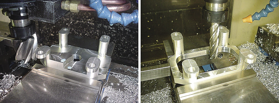
Figure 1a (left): This setup was chosen based on using the longest contact area possible with the vise jaws.
Figure 1b (right): As the “window” cut nears completion, the parts become much weaker. Lighter cuts must be taken at this stage.
Images courtesy J. Harvey.
- Determine if you can machine a job holding the material in a standard milling machine vise. Use a vise when possible. A vise eliminates a lot of variables, including concerns about accuracy and rigidity of the workholding device. A high-quality vise is inherently accurate and rigid.
- Use multiple matched vises to hold long parts. Indicating multiple vises in line may take some time. However, once the vises are in place, they can usually be left alone for a while. Multiple vises can be used to run multiples of the same part with different starting points, such as G54, G55 or G56.
- Determine how you are going to square the material. Squaring the five sides of a part that are accessible in a setup means you must side-mill four sides. The top surface can be facemilled. Side-milled surfaces are more prone to inaccuracies than facemilled ones. An endmill used for side milling that is dull, chipped or tapered will impart a poor finish. This is especially true for long endmills. Therefore, to ensure accuracy when side-milling a surface, apply a new endmill.
- Square large, tight-tolerance parts independently. In other words, concentrate on getting good blanks first, then use other programs to add the necessary features.
- Plan for material warpage. Warpage is a fact of life when machining; it is often an issue that must be addressed, especially with long, slender and hogged parts. It may not be much of an issue on stocky, blocky parts or parts that need just a few simple features. One of the most effective ways to eliminate the tendency of material to warp is to cut through the skin of the stock material before doing any other precision machining operations.
About the Author: James A. Harvey is a machinist and plastic moldmaker who has worked in shops across the U.S. for nearly 40 years. Harvey’s column is adapted from information in his book “CNC Trade Secrets: A Guide to CNC Machine Shop Practices,” published by Industrial Press Inc., South Norwalk, Conn. The publisher can be reached by calling (888) 528-7852 or visiting www.industrialpress.com. By indicating the code CTE20OFF when ordering, CTE readers will receive a 20 percent discount off the book’s list price of $29.95.
Related Glossary Terms
- chatter
chatter
Condition of vibration involving the machine, workpiece and cutting tool. Once this condition arises, it is often self-sustaining until the problem is corrected. Chatter can be identified when lines or grooves appear at regular intervals in the workpiece. These lines or grooves are caused by the teeth of the cutter as they vibrate in and out of the workpiece and their spacing depends on the frequency of vibration.
- computer numerical control ( CNC)
computer numerical control ( CNC)
Microprocessor-based controller dedicated to a machine tool that permits the creation or modification of parts. Programmed numerical control activates the machine’s servos and spindle drives and controls the various machining operations. See DNC, direct numerical control; NC, numerical control.
- computer-aided design ( CAD)
computer-aided design ( CAD)
Product-design functions performed with the help of computers and special software.
- endmill
endmill
Milling cutter held by its shank that cuts on its periphery and, if so configured, on its free end. Takes a variety of shapes (single- and double-end, roughing, ballnose and cup-end) and sizes (stub, medium, long and extra-long). Also comes with differing numbers of flutes.
- feed
feed
Rate of change of position of the tool as a whole, relative to the workpiece while cutting.
- gang cutting ( milling)
gang cutting ( milling)
Machining with several cutters mounted on a single arbor, generally for simultaneous cutting.
- milling
milling
Machining operation in which metal or other material is removed by applying power to a rotating cutter. In vertical milling, the cutting tool is mounted vertically on the spindle. In horizontal milling, the cutting tool is mounted horizontally, either directly on the spindle or on an arbor. Horizontal milling is further broken down into conventional milling, where the cutter rotates opposite the direction of feed, or “up” into the workpiece; and climb milling, where the cutter rotates in the direction of feed, or “down” into the workpiece. Milling operations include plane or surface milling, endmilling, facemilling, angle milling, form milling and profiling.
- milling machine ( mill)
milling machine ( mill)
Runs endmills and arbor-mounted milling cutters. Features include a head with a spindle that drives the cutters; a column, knee and table that provide motion in the three Cartesian axes; and a base that supports the components and houses the cutting-fluid pump and reservoir. The work is mounted on the table and fed into the rotating cutter or endmill to accomplish the milling steps; vertical milling machines also feed endmills into the work by means of a spindle-mounted quill. Models range from small manual machines to big bed-type and duplex mills. All take one of three basic forms: vertical, horizontal or convertible horizontal/vertical. Vertical machines may be knee-type (the table is mounted on a knee that can be elevated) or bed-type (the table is securely supported and only moves horizontally). In general, horizontal machines are bigger and more powerful, while vertical machines are lighter but more versatile and easier to set up and operate.
- precision machining ( precision measurement)
precision machining ( precision measurement)
Machining and measuring to exacting standards. Four basic considerations are: dimensions, or geometrical characteristics such as lengths, angles and diameters of which the sizes are numerically specified; limits, or the maximum and minimum sizes permissible for a specified dimension; tolerances, or the total permissible variations in size; and allowances, or the prescribed differences in dimensions between mating parts.
Author

James A. Harvey is a machinist and moldmaker who has worked in shops across the U.S. for nearly 40 years. Harvey’s Shop Operations column for Cutting Tool Engineering magazine is adapted from information in his book “CNC Trade Secrets: A Guide to CNC Machine Shop Practices,” published by Industrial Press Inc., South Norwalk, Conn. The publisher can be reached by calling (888) 528-7852 or visiting www.industrialpress.com. By indicating the code CTE20OFF when ordering, CTE readers will receive a 20 percent discount off the book’s list price of $29.95.