Significant developments in CAD and CAM functionality in the latest release of VISI, from Vero Software, give users additional speed and quality throughout their design and machining processes. VISI Brand Manager Massimo Vergerio says CAD updates in VISI 2017 R1 are focusing on the user experience and adding enhancements to allow customers to speed up their design process.
Examples of these include:
- Speed improvement to the picking process with support for dynamic ‘drag & drop’
- Dynamic zoom to and from an area on the screen by holding down the space bar “This is particularly valuable to zoom in on a particular aspect of a large component on screen.”
- Intelligent chaining for joining wireframe elements together
- Single right-hand mouse click to confirm commands, instead of ticking a box with a keystroke
And for CAM, an update to geometry management means individual pieces are no longer limited by a specific project. “It gives greater freedom in picking the piece, obstacle or stock, allowing any combination. This is also used for picking faces and face lists, all managed in a much more user-friendly interface, and driven inside the operation itself. Everything is now linked to the operation, not the project, and all geometry is managed interactively, picking the specific pieces or faces that we want to machine.”
Amongst dozens of individual updates to VISI’s CAD functionality:
Several auto-ballooning enhancements have been made within the Assembly Manager, providing additional control when adding BOM ballooning within the plotview. These include automatic positioning using multiple axes and removal of duplicated balloons, providing clearer results.
The creation of manufacturing drawing data has been improved by the addition of a number of “view property” settings. To simplify the creation of cut-away views of complex geometry, “outbreak section depths” can be automatically measured and edited by on-screen selection.
Model properties can be set during the Modelling process. VISI Product Support Manager John Cockerill says: “Any model manufacturing and purchasing data can be added and controlled by simply selecting the model geometry from the working environment. Added data is automatically inserted into the Assembly Manager interface, providing a more interactive method of controlling modelling data.”
New functionality has been added to the Mold Design module, allowing the user to validate the effect of a cooling channel circuit. Size and positioning can be effortlessly extracted from model geometry and inserted into the Cooling Validations step-by step workflow for a thermal analysis of a mold’s temperature conditioning system.
For VISI Flow modules, the precision of warpage calculations has been enhanced by adjustments within the filling & holding algorithms. These adjustments take advantage of additional data within the material database, which has been increased with the addition on new material grades.
For VISI Progress users, a number of Strip enhancements include the ability to manipulate a strip’s width, height and component angle from the graphics area, which simplifies the strip layout process. In addition, calculated Shear / Bending / Flange stress data is provided for every individual step of a strip’s development.
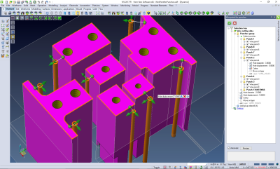
Also added for Progress users is a new function for automatically creating wire points for tooling punches. The diameter / position and multiple start points are all managed from the graphic area interface. All created wire data is automatically recognized within the CAM and Wire modules.
Improvements to the CLS License Manager now give the ability to create specific profiles and options for each user operating across a multi-seat network.
Vero Software’s powerful and game-changing Waveform roughing technology is included for VISI machining. Waveform’s proven cutting strategies increase material removal rates and productivity while prolonging tooling life. The high-speed machining strategy maintains a constant tool cutting load by ensuring consistent tool engagement with the material.
On Rest Roughing, instead of having to create separate dynamic incremental stock based on the previous operation, VISI 2017 R1 handles the process automatically. “The user simply picks the previous operation, and the system automatically creates this stock within the operation.” This is invaluable for 3+2 work knowing that the correct stock will be used on the tilted operations.
Again, specific Vero Group technology – this time a new, specially-developed engine – is creating a new profiling strategy for 2D milling. John Cockerill says it improves reliability and output, and provides multiple options for cornering, used for keeping or removing sharp corners on profiles. Old profiling will be converted automatically, and there are improvements to speed, obstacle and cutter compensation management, along with intelligent collision checking.
Contact Details
Related Glossary Terms
- computer-aided design ( CAD)
computer-aided design ( CAD)
Product-design functions performed with the help of computers and special software.
- computer-aided manufacturing ( CAM)
computer-aided manufacturing ( CAM)
Use of computers to control machining and manufacturing processes.
- cutter compensation
cutter compensation
Feature that allows the operator to compensate for tool diameter, length, deflection and radius during a programmed machining cycle.
- gang cutting ( milling)
gang cutting ( milling)
Machining with several cutters mounted on a single arbor, generally for simultaneous cutting.
- milling
milling
Machining operation in which metal or other material is removed by applying power to a rotating cutter. In vertical milling, the cutting tool is mounted vertically on the spindle. In horizontal milling, the cutting tool is mounted horizontally, either directly on the spindle or on an arbor. Horizontal milling is further broken down into conventional milling, where the cutter rotates opposite the direction of feed, or “up” into the workpiece; and climb milling, where the cutter rotates in the direction of feed, or “down” into the workpiece. Milling operations include plane or surface milling, endmilling, facemilling, angle milling, form milling and profiling.
- profiling
profiling
Machining vertical edges of workpieces having irregular contours; normally performed with an endmill in a vertical spindle on a milling machine or with a profiler, following a pattern. See mill, milling machine.


