Courtesy of All images: Ingersoll Cutting Tools
Raising the spindle speed and lowering the DOC actually reduced the chip load despite doubling the feed rate and the volumetric removal rate when SPX applied Ingersoll Power Feed Plus tools.
Case histories and comments about hard milling in die and mold shops.
Milling hard die and mold parts can be either a boon or a nightmare, depending on the approach. For one, rigidity of the entire cutting system—from machine base to cutting zone—is essential. For another, inserts with a fine submicron-grain carbide substrate markedly improve edge life because they present uniformly dense carbide right at the cutting edge. Even so, inserts cutting 45-HRC and harder tool steel inevitably wear faster than they would when cutting aluminum.
Beyond that, application-specific factors and how die and mold shops read them can swing the balance in their favor.
With that in mind, this article presents three different case studies involving hard milling at die and mold shops and the lessons they provide.
Protecting a Light-Duty Machine
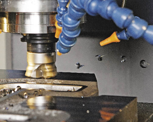
SPX is a 600-employee, 20-hours-a-day/5-days-a-week steel forging house in Owatonna, Minn. The die shop that services the main plant is small, with a limited inventory of general-purpose machine tools. A substantial part of its workload consists of repairing worn die sets, which by nature are hardened.
One of the mainstay machines is an OKK 40-taper vertical machining center with a 14,000-rpm spindle equipped with ceramic bearings. Being a light-duty machine, it may be great for fine cavity work on new dies before they’re hardened, but it is nobody’s first choice for a steady diet of restoring worn dies in 43-HRC Finkle forging die stock.
The first step in die repair is to skin off about ⅜ " of a die set’s mating surfaces to create enough stock for resinking the cavities—essentially flat facemilling. The previous standard practice was to run a 2¼ "-dia., 4-flute, positive-rake facemill at a 500-rpm spindle speed, a 50-ipm feed rate and a 0.030 " DOC. Even at this low feed rate, hammering problems often arose, necessitating a lower feed to protect the machine—especially its ceramic spindle bearings.
“Protecting the machine is our No. 1 priority because we don’t have much backup,” said Cory Pleshcourt, SPX die maker.
The retooling began when Pleshcourt asked Ondrej Lubinski, an Ingersoll field engineer, for tooling ideas that would prevent damage to the light-duty machine in this heavy-duty task.
Because the spindle is capable of much higher speeds, Lubinski suggested a smaller 3-flute Power Feed Plus mill from Ingersoll Cutting Tools with submicron- carbide inserts and feeding it faster but shallower. The cutter is positive radially but negative axially. The shop tested the new cutter at various settings, finally settling on twice the previous feed and one third less depth: 1,000 rpm, 100 ipm and a 0.020 " DOC. Although the machine removed metal about 10 percent faster, the spindle load meter read 15 percent lower and all signs of hammering disappeared. Insert life doubled.
It may seem counterintuitive to switch to a cutter with fewer flutes to deter hammering, because the total work is spread less widely. But in combination with increasing rpm and feed and reducing the DOC, the chip load per tooth decreased, as did the cutting forces transmitted back into the spindle and machine frame.
The negative axial rake makes double-sided inserts possible, providing more edges in an operation where tools wear quickly.
“With lower-power machines running hard parts, reducing the flute count in the cutter reduces friction, conserving scarce horsepower for actual chipmaking,” explained Lubinski.
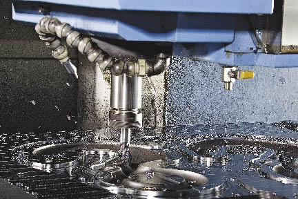
Faster Facing
Although the 25-man die shop at Crosby-Lebus Manufacturing Co., Longview, Texas, seems to face basically the same workload as SPX, its tooling solutions are different because C-L has higher-power machines and works on much larger die sets. C-L machines die sets that measure from 12 "×12 " to 50 "×60 " and are typically made of Finkle No. 2 forging die stock hardened to 38 to 42 HRC.
C-L was satisfied with a 15-ipm feed rate, at 650 rpm and a 0.100 " DOC for skin milling using a 2½ " conventional zero-rake finishing mill. Then, at an Ingersoll customer seminar in Rockford, Ill., C-L machinist Sidney Maxwell saw a Hi Feed Deka cutter feeding at 150 ipm on hardened stock. Back in Longview a week later, Maxwell, programmer Buddy Walston and Ingersoll field engineer Ernie Schooley tested a Hi Feed Deka cutter of the same size on C-L’s hardened stock, and the tool achieved the same result. The new standard settings for skinning the hardened dies rose to 150 ipm, 850 rpm and a 0.035 " DOC. “We traded off a little cut depth for a tenfold gain in feed, and I’ll take that any day,” Walston said. “A job that used take 90 minutes now takes 12.”
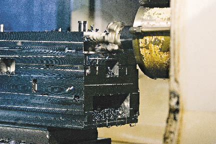
The free-cutting Hi Feed Deka cutter handles 150-ipm feeds when cutting hardened Finkle No. 2 die stock at Crosby-Lebus.
The key physical differences in the cutters include a positive rake for freer cutting and a sturdier insert with a robust wear land that trails the cutting edge. The Hi Feed Deka inserts also provide 10 cutting edges vs. the previous four. Edge life more than tripled.
The faster skinning operation enabled C-L to move it to a separate machine, freeing the more sophisticated CNC machines for cavity work only and streamlining the reconditioning cycle.
Punishing Sandwich
A key part of Precision Mold Base Corp.’s flagship product is a metal sandwich with mild steel or gummy stainless steel as the bread and 4140 steel hardened to 33 to 35 HRC as the filling. PMBC, Tempe, Ariz., has to rough mill the workpiece edge, exposing the cutter to two vastly different metals in the same pass. Worse yet, gaps in the toolpath caused by previous operations leave the tool alternately cutting air and then slamming into the hardest metal. Finally, alignment variations in the sandwich assemblies swing the DOC unpredictably between 0.060 " and 0.250 ".
“It’s the most punishing job in our place,” said foreman Romney D’Antuono. “We have a shelf littered with wrecked or burnt button cutters to show for it. We call it our ‘morgue.’ ”
Previously, PMBC’s process was to rough mill the edges with a five-insert, zero-rake button cutter. The parameters were 25 ipm at 550 rpm and a 0.060 " DOC, as well as a 3.700 " radial engagement. It was slow going, with inserts often rupturing mid-cut. With the switch to a positive-rake Ingersoll Form-Master Plus cutter, the operation runs 2½ times faster, with insert edge life extending to at least two shifts—reliably—vs. sometimes failing in the first cut. With the greater edge security, PMBC now runs the operation “lights out.” The new settings are 55 ipm, 440 rpm and a 0.190 " DOC.
The gain stems largely from the high-positive rake angle, which creates a free-cutting, cleaving action that reduces cutting forces on the tool, workpiece and machine.
The cutter also has two additional inserts, to more widely distribute the cutting loads. The inserts have smooth top faces, with no chipbreakers.
“You can hear the difference,” said D’Antuono. “The old operation caused a lot of pounding and scraping. Now it purrs like a kitten.”
Originally, D’Antuono balked at the Form-Master Plus price tag, about 30 percent higher than the old button cutter, with inserts costing 10 percent more. He figured that to achieve payback, the new cutter would have to run at least 30 percent faster, with inserts lasting 30 percent longer. “Given the gruesome cutting conditions, it simply didn’t seem possible.”
It took a live test to convince him. He and Ingersoll field engineer George O’Gar selected a mold base measuring 18 "×12 "×12 " with bad alignment between the layers, and set it up on a 35-hp Mazak Ultra 650 horizontal machining center with a 50-taper spindle. They started conservatively at 40 ipm, but even so they were removing metal twice as fast as before. They settled on a 55-ipm feed with a 0.190 " DOC.
Today that “abusive” operation runs two-and-a-half times faster, inserts last four to five times longer, and catastrophic insert failure has been eliminated. “Now the inserts wear gradually, over a couple of shifts, to a predictable end point,” D’Antuono said. Edge life is so reliable that he can run the operation “lights out” without slowing down more than 10 percent.
What to Look For
As these cases illustrate, there is no single “right tool” or “right machine” for hard milling. A lot depends on workpiece geometry and what share of the total machining workload hard milling represents.
Nevertheless a few basic principles apply.
Machine—look for rigidity from the base and frame to the box ways and cutting zone.
Spindle—should be rated to 20,000 rpm to enable higher feeds and shallower cuts, ultimately improving throughput while reducing chip load. The spindle should have ceramic bearings, hydraulic tool clamping and features to minimize heat flow and thermal expansion back through the spindle and machine frame. Ideally, the spindle should have high-pressure through-spindle air (as well as the usual liquid coolant for possible aluminum and stainless steel work) to reduce heat buildup and promote good chip evacuation. Remember, getting rid of chips gets rid of heat and the risk of recutting.
Above: Despite “hyper interrupted cuts” and varying alignments and physical properties of the respective metals, the Ingersoll Form Master facemill cuts smoothly through a bimetal workpiece at Precision Mold Base. Throughput is up two-and-a-half times vs. the previous zero-rake button cutter, and cutting edges last four to five times as long.
Fixturing—focus on maximum rigidity to withstand the much higher cutting forces required for hard milling and help minimize vibration during machining. The cuts may be smaller dimensionally, but in most cases making a small chip of hard metal creates higher forces than making a big chip of soft metal.
Machine controls—the large data files associated with contour milling require ample look-ahead capabilities and large memory storage capacity.
Software—an advanced CAM system is critical for hard-part contouring to keep the chip load uniform during the machining process. The more axes you work in, the more advanced the CAM system you’ll need. Uniform chip load is especially critical in hard milling because both the cutting forces and temperatures are high, causing cutting edges to wear faster. The software should ensure the programmed toolpath prevents the cutter from accidentally encountering large amounts of uncut stock. Higher-capability software is especially valuable in die and mold work, where every workpiece can be different.
Tooling—choose robustly designed cutter bodies with secure insert seating. Inserts should be a favorable submicron grade and have a wear-resistant coating, such as TiAlN, and should incorporate free-cutting geometries that cleave rather than scrape off the stock. Do everything possible to minimize the consequences of the inevitable transient impact forces that arise when a hard piece of carbide slams into hard metal in a stiff cutting platform.
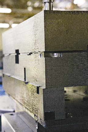
Left: An irregular edge and two different metals of varying hardness and machinability made the facemilling operation challenging for Precision Mold Base. The outside layers are 836 mild steel or 410 stainless steel and the center is 4120 tool steel, hardened to 32 to 35 HRC.
Everything Matters More
You may not be able to see or hear the differences in the cutting forces when hard milling, but they definitely exist. Don’t let your eyes and ears be fooled. Instability in any of the many variables associated with hard milling can become a source for vibration and chatter that quickly spreads, ending up at the business end of the tool. Everything that matters in milling matters more in hard milling.
Above all, get to know your machine, tooling, controls, fixturing and software before you start. Take the time to analyze the task more carefully than you would for milling aluminum or wrought steel. Pay special attention to maintaining consistent chip load and predictable cutting conditions. Utilize your CAM system to the fullest to ensure this. Beware of even the slightest vibration.
Finally, ask for help from qualified vendors. There’s a lot of knowledge on hard milling available for the asking. You’ll get better answers sooner and avoid more problems. CTE
About the author: Bill Fiorenza is product manager-die and mold for Ingersoll Cutting Tools, Rockford, Ill. For more information about the company’s cutting tools, call (815) 387-6600, visit www.ingersoll-imc.com or enter #310 on the IS card.
Related Glossary Terms
- axial rake
axial rake
On angular tool flutes, the angle between the tooth face and the axial plane through the tool point.
- button cutter
button cutter
Round insert that is able to spread the stresses generated by the cutting forces over a larger area than other insert shapes. However, a round insert generates higher axial forces, which transfer into the workpiece.
- chatter
chatter
Condition of vibration involving the machine, workpiece and cutting tool. Once this condition arises, it is often self-sustaining until the problem is corrected. Chatter can be identified when lines or grooves appear at regular intervals in the workpiece. These lines or grooves are caused by the teeth of the cutter as they vibrate in and out of the workpiece and their spacing depends on the frequency of vibration.
- computer numerical control ( CNC)
computer numerical control ( CNC)
Microprocessor-based controller dedicated to a machine tool that permits the creation or modification of parts. Programmed numerical control activates the machine’s servos and spindle drives and controls the various machining operations. See DNC, direct numerical control; NC, numerical control.
- computer-aided manufacturing ( CAM)
computer-aided manufacturing ( CAM)
Use of computers to control machining and manufacturing processes.
- coolant
coolant
Fluid that reduces temperature buildup at the tool/workpiece interface during machining. Normally takes the form of a liquid such as soluble or chemical mixtures (semisynthetic, synthetic) but can be pressurized air or other gas. Because of water’s ability to absorb great quantities of heat, it is widely used as a coolant and vehicle for various cutting compounds, with the water-to-compound ratio varying with the machining task. See cutting fluid; semisynthetic cutting fluid; soluble-oil cutting fluid; synthetic cutting fluid.
- facemill
facemill
Milling cutter for cutting flat surfaces.
- facemilling
facemilling
Form of milling that produces a flat surface generally at right angles to the rotating axis of a cutter having teeth or inserts both on its periphery and on its end face.
- feed
feed
Rate of change of position of the tool as a whole, relative to the workpiece while cutting.
- flat ( screw flat)
flat ( screw flat)
Flat surface machined into the shank of a cutting tool for enhanced holding of the tool.
- flutes
flutes
Grooves and spaces in the body of a tool that permit chip removal from, and cutting-fluid application to, the point of cut.
- gang cutting ( milling)
gang cutting ( milling)
Machining with several cutters mounted on a single arbor, generally for simultaneous cutting.
- hardness
hardness
Hardness is a measure of the resistance of a material to surface indentation or abrasion. There is no absolute scale for hardness. In order to express hardness quantitatively, each type of test has its own scale, which defines hardness. Indentation hardness obtained through static methods is measured by Brinell, Rockwell, Vickers and Knoop tests. Hardness without indentation is measured by a dynamic method, known as the Scleroscope test.
- inches per minute ( ipm)
inches per minute ( ipm)
Value that refers to how far the workpiece or cutter advances linearly in 1 minute, defined as: ipm = ipt 5 number of effective teeth 5 rpm. Also known as the table feed or machine feed.
- land
land
Part of the tool body that remains after the flutes are cut.
- look-ahead
look-ahead
CNC feature that evaluates many data blocks ahead of the cutting tool’s location to adjust the machining parameters to prevent gouges. This occurs when the feed rate is too high to stop the cutting tool within the required distance, resulting in an overshoot of the tool’s projected path. Ideally, look-ahead should be dynamic, varying the distance and number of program blocks based on the part profile and the desired feed rate.
- machinability
machinability
The relative ease of machining metals and alloys.
- machining center
machining center
CNC machine tool capable of drilling, reaming, tapping, milling and boring. Normally comes with an automatic toolchanger. See automatic toolchanger.
- milling
milling
Machining operation in which metal or other material is removed by applying power to a rotating cutter. In vertical milling, the cutting tool is mounted vertically on the spindle. In horizontal milling, the cutting tool is mounted horizontally, either directly on the spindle or on an arbor. Horizontal milling is further broken down into conventional milling, where the cutter rotates opposite the direction of feed, or “up” into the workpiece; and climb milling, where the cutter rotates in the direction of feed, or “down” into the workpiece. Milling operations include plane or surface milling, endmilling, facemilling, angle milling, form milling and profiling.
- milling machine ( mill)
milling machine ( mill)
Runs endmills and arbor-mounted milling cutters. Features include a head with a spindle that drives the cutters; a column, knee and table that provide motion in the three Cartesian axes; and a base that supports the components and houses the cutting-fluid pump and reservoir. The work is mounted on the table and fed into the rotating cutter or endmill to accomplish the milling steps; vertical milling machines also feed endmills into the work by means of a spindle-mounted quill. Models range from small manual machines to big bed-type and duplex mills. All take one of three basic forms: vertical, horizontal or convertible horizontal/vertical. Vertical machines may be knee-type (the table is mounted on a knee that can be elevated) or bed-type (the table is securely supported and only moves horizontally). In general, horizontal machines are bigger and more powerful, while vertical machines are lighter but more versatile and easier to set up and operate.
- payload ( workload)
payload ( workload)
Maximum load that the robot can handle safely.
- rake
rake
Angle of inclination between the face of the cutting tool and the workpiece. If the face of the tool lies in a plane through the axis of the workpiece, the tool is said to have a neutral, or zero, rake. If the inclination of the tool face makes the cutting edge more acute than when the rake angle is zero, the rake is positive. If the inclination of the tool face makes the cutting edge less acute or more blunt than when the rake angle is zero, the rake is negative.
- sawing machine ( saw)
sawing machine ( saw)
Machine designed to use a serrated-tooth blade to cut metal or other material. Comes in a wide variety of styles but takes one of four basic forms: hacksaw (a simple, rugged machine that uses a reciprocating motion to part metal or other material); cold or circular saw (powers a circular blade that cuts structural materials); bandsaw (runs an endless band; the two basic types are cutoff and contour band machines, which cut intricate contours and shapes); and abrasive cutoff saw (similar in appearance to the cold saw, but uses an abrasive disc that rotates at high speeds rather than a blade with serrated teeth).
- titanium aluminum nitride ( TiAlN)
titanium aluminum nitride ( TiAlN)
Often used as a tool coating. AlTiN indicates the aluminum content is greater than the titanium. See coated tools.
- toolpath( cutter path)
toolpath( cutter path)
2-D or 3-D path generated by program code or a CAM system and followed by tool when machining a part.