In addition to needing a machine tool that can perform both additive manufacturing, such as laser metal deposition, and subtractive machining, hybrid manufacturing requires a CAD/CAM software package that accommodates building and removing material.
One such package is hyperMill from Needham, Massachusetts-based Open Mind Technologies USA Inc., a subsidiary of Open Mind Technologies AG in Wessling, Germany.
“Hybrid to us is very similar to subtractive machining in some ways where we are using many strategies for planar and nonplanar building materials followed by the machining process to typically bring a slight oversize condition to a finished component,” said Managing Director Alan Levine. “Additionally, on the hybrid side we’ve built in the necessary technology to properly control the heat source whether it’s powder- or wire-based.”
He said the foundation of the hybrid manufacturing market began with powder bed, which is considered a simpler method than the directed energy deposition technique. However, when manufacturers want to add a hard coating of material to repair a part, such as a mold, turbine blade or disc brake, they tend to turn to directed energy deposition.
Lothar Glasmacher, head of additive and process technologies at ModuleWorks GmbH in Aachen, Germany, said other common hybrid applications include building aerospace parts like blisks and propellers; prototyping structural parts, including those made of multiple workpiece materials; and creating modular parts that cannot be machined from stock material because of their part geometry. The company developed software for MU-V Laser EX hybrid machines from Okuma Corp. that combines additive path planning and subtractive toolpath calculation components.

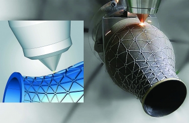
Material is added to an aerospace nozzle using hyperMill CAD/CAM software from Open Mind Technologies. Image courtesy of Open Mind Technologies USA
He said ModuleWorks can deliver single modules to close the complete process chain from workpiece input to path planning and simulation to NC output. With its post-processing framework, the company is able to send the appropriate NC code and specific commands to any machine or controller for additive manufacturing.
“The closed-chain manufacturing from CAD to the hybrid machine allows productive part manufacturing without manual toolpath editing or teaching,” Glasmacher said.
In addition, he said 3D constant step-over and offset slicing for additive path planning ensure a stable additive process without gaps in the weld bead. This capability provides a smooth look-ahead function for five-axis orientation motions and effective mesh- and surface-based path planning.
New Versus Repaired Parts
Another CAD/CAM package for additive and hybrid manufacturing, such as programming cladding on five-axis milling and mill/turn machines, is available from SprutCAM America in Waunakee, Wisconsin. Founded in Naberezhnye Chelny, Russia, SprutCAM Technology Ltd. also has an office in Germany.
According to one Greek client, 95% of its applications are for part restoration with revisions and corrections accounting for the remainder. Another customer from Greece noted that restoration accounts for 100% of company applications, including propellers, propeller shafts, turbine shafts and turbine impellers. Both companies concurred that there are no problems with integrating the CAD and CAM systems in SprutCAM’s software.
Nonetheless, Glasmacher said one of the main deficits of conventional CAD/CAM systems is that they are positioned well in the milling area but do not offer effective additive solutions to optimally support the process. As a result, an operator often has to use several systems that interact with each other in a cumbersome manner, and a continuity from component preparation to hybrid path planning to NC output therefore is not possible. However, he said this chain can be closed because of ModuleWorks’ expertise in both subtractive and additive applications.

Technicians program an Okuma MU-V Laser EX hybrid machine using software from ModuleWorks. Image courtesy of ModuleWorks
Levine agreed that integration of the CAD and CAM sides is not an issue for hyperMill software.
“For us, you are simultaneously working in the CAD and CAM environments,” he said. “It’s very easy to access any functions you need at any time.”
Lattice Optimization
Glasmacher said lattice support structures, which only can be produced additively, make it possible to reduce the weight and amount of workpiece material with constant mechanical properties.
“The combination of lattice structures and additive processes has also created a completely new possibility for component design,” he said.
“Parts with lattice structures are typically made with a powder bed 3D printer,” said David Bourdages, product manager for hyperMill at Open Mind Technologies. “The functional areas of these parts often require finishing, as well as some machining oper-ations, to remove the support structure. Because parts are not perfect and the clamping is done on (a) raw model, hyperMill offers a best-fit automation capability, which finds the best position of the theoretical part in the existing 3D-printed part. The CAM software should also offer tools to generate an adequate toolpath for finishing the functional areas and for removing the support structure while keeping track of the stock.”
Offsetting Not Needed
However, Glasmacher said there is no need to manually offset a part with ModuleWorks. Options exist instead to add offsets to any part of a model, and this occurs with path cycle calculation. For example, a user can give additional or negative offsets to surfaces and curves. This capability can compensate for differences from a CAD model to an actual part or add more material than needed for extra protection during machining.
Another challenge when hybrid manufacturing is to manage tolerance stackup across additive and subtractive operations. Overall, he said ModuleWorks has optimized toolpath planning to avoid layer stackup, such as with automatic starting point rotation and process control features on the toolpath, which are designed for continuous buildup per layer. After depositing each layer, the software can combine a scanning operation and a layer adjustment for the next layer.
Resolving Heat Distortion
Bourdages said to help resolve any heat distortion issues that occur during hybrid manufacturing, research continues on an industrywide basis.
“There is much to learn, and it’s really complex,” he said. “This will evolve. But for now, knowing all the parameters and how they are connected to each other is not predictable.”

Open Mind Technologies’ hyperMill CAD/CAM software enables hybrid manufacturing, such as this additive operation. Image courtesy of Open Mind Technologies USA
Levine said engineers currently apply common sense to solve problems. For instance, when creating a long, slender rectangle, rather than moving in the shorter direction and focusing heat in one area for an extended time, long strokes might be taken so the heat in one area cools down before returning to it.
“In the future,” he said, “technology and analysis will guide people toward better build processes that will be cognizant of thermal situations and distortions.”
To avoid overheating a workpiece, Glasmacher said ModuleWorks provides special path planning strategies like sorting strategies about how to build up material. In addition to the path calculation, temperature behavior can be taken into account via NC code. For example, waiting commands can be inserted into NC code through the “posting framework,” which can be switched depending on part geometry.
Thermal distortion ultimately is a complex, largely uncontrollable process influenced by numerous factors, such as indoor and outdoor temperature, humidity and the season, according to SprutCAM’s customers, which rely on experience in 99% of cases.
When selecting CAD/CAM software for hybrid manufacturing, Levine recommends that end users first understand how simple or complex their parts are and then consider not just the theoretical experience of a software developer but its real-world experience working with partners.
“We know some of our partners have choices, but we believe they are using our system nearly exclusively,” he said. “That helps with knowledge exchange and building up the experience base.”
Although hybrid manufacturing has been performed for years, Levine said the market still is burgeoning.
“Broad usage is not quite there in the market,” he said.
For more information about hybrid manufacturing, view video presentations by ModuleWorks and Open Mind Technologies USA at www.ctemag.com by entering this URL on your web browser: cteplus.delivr.com/2ep9s
Contact Details
Contact Details
Related Glossary Terms
- computer-aided design ( CAD)
computer-aided design ( CAD)
Product-design functions performed with the help of computers and special software.
- computer-aided manufacturing ( CAM)
computer-aided manufacturing ( CAM)
Use of computers to control machining and manufacturing processes.
- gang cutting ( milling)
gang cutting ( milling)
Machining with several cutters mounted on a single arbor, generally for simultaneous cutting.
- lapping compound( powder)
lapping compound( powder)
Light, abrasive material used for finishing a surface.
- look-ahead
look-ahead
CNC feature that evaluates many data blocks ahead of the cutting tool’s location to adjust the machining parameters to prevent gouges. This occurs when the feed rate is too high to stop the cutting tool within the required distance, resulting in an overshoot of the tool’s projected path. Ideally, look-ahead should be dynamic, varying the distance and number of program blocks based on the part profile and the desired feed rate.
- mechanical properties
mechanical properties
Properties of a material that reveal its elastic and inelastic behavior when force is applied, thereby indicating its suitability for mechanical applications; for example, modulus of elasticity, tensile strength, elongation, hardness and fatigue limit.
- milling
milling
Machining operation in which metal or other material is removed by applying power to a rotating cutter. In vertical milling, the cutting tool is mounted vertically on the spindle. In horizontal milling, the cutting tool is mounted horizontally, either directly on the spindle or on an arbor. Horizontal milling is further broken down into conventional milling, where the cutter rotates opposite the direction of feed, or “up” into the workpiece; and climb milling, where the cutter rotates in the direction of feed, or “down” into the workpiece. Milling operations include plane or surface milling, endmilling, facemilling, angle milling, form milling and profiling.
- numerical control ( NC)
numerical control ( NC)
Any controlled equipment that allows an operator to program its movement by entering a series of coded numbers and symbols. See CNC, computer numerical control; DNC, direct numerical control.
- process control
process control
Method of monitoring a process. Relates to electronic hardware and instrumentation used in automated process control. See in-process gaging, inspection; SPC, statistical process control.
- step-over
step-over
Distance between the passes of the toolpath; the path spacing. The distance the tool will move horizontally when making the next pass. Too great of a step-over will cause difficulty machining because there will be too much pressure on the tool as it is trying to cut with too much of its surface area.
- tolerance
tolerance
Minimum and maximum amount a workpiece dimension is allowed to vary from a set standard and still be acceptable.
- toolpath( cutter path)
toolpath( cutter path)
2-D or 3-D path generated by program code or a CAM system and followed by tool when machining a part.
- web
web
On a rotating tool, the portion of the tool body that joins the lands. Web is thicker at the shank end, relative to the point end, providing maximum torsional strength.
Contributors
ModuleWorks GmbH
+49 241 9900040
www.moduleworks.com
Open Mind Technologies USA Inc.
888-516-1232
www.openmind-tech.com
SprutCAM America
608-849-4430
www.sprutcamamerica.com


