All-Directional Y-Axis Turning
All-Directional Y-Axis Turning
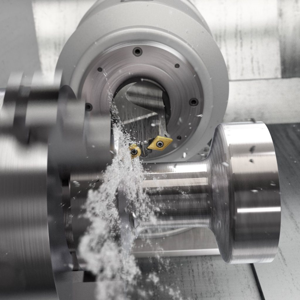
So how does Y-axis turning work? As the name implies, the new method makes use of the Y-axis, and all three axes are used simultaneously when machining. The tool rotates around its own center, the insert is placed for machining in the Y-Z plane and the milling spindle axis interpolates during turning. This allows intricate shapes to be machined with a single tool.

Sandvik Coromant, a cutting tool and tooling system specialist, has introduced a new method for turning complicated shapes and pockets with a single tool. Y-axis turning offers benefits such as reduced cycle time, improved component surface quality and more stable machining.
Turning has developed immensely in recent years with new innovations, such as all-directional PrimeTurning™, non-linear turning and interpolation turning. "One could say that these advances, together with progressive capabilities in modern machines and CAM software, have paved the way for the new Y-axis turning method," says Staffan Lundström, Product Manager, Turning, at Sandvik Coromant. "And with the tools and method now in place, we look forward to exploring the possibilities this method can present to our customers."
So how does Y-axis turning work? As the name implies, the new method makes use of the Y-axis, and all three axes are used simultaneously when machining. The tool rotates around its own center, the insert is placed for machining in the Y-Z plane and the milling spindle axis interpolates during turning. This allows intricate shapes to be machined with a single tool.
Y-axis turning offers numerous benefits. The ability to machine several features with a single tool reduces cycle time, and no tool changes are required, which minimizes the risk of "blend points," or irregularities between adjacent machined surfaces. The main cutting forces are directed into the machine spindle, thus improving stability and reducing the risk of vibration. A constant entering angle drastically improves chip control and makes it easier to avoid chip jamming.
Two new tools have been developed to support Y-axis turning. The new CoroTurn® Prime variant is suitable for shafts, flanges and components with undercuts. The CoroPlex® YT twin-tool, featuring CoroTurn TR profiling inserts and CoroTurn 107 round inserts with rail interface, can favorably be used for components with pockets and cavities.
To summarize, Y-axis turning is a method for simultaneous three-axis turning with interpolation of the milling spindle axis. The new tools can also be used in "static mode" with a locked spindle for flexible two-axis turning with fast insert indexing. The method is suitable for all materials and requires a multitask machine with options to allow interpolation of the milling spindle axis during turning."


