Alphacam 2018 RI Software
Alphacam 2018 RI Software
The 2018 R1 release of Alphacam, from Vero Software, includes considerable enhancements to automation and nesting functions. There is now the ability in Automation Manager to have a connection between "parent-child" parts, as job files can now be added to another job file as a sub-component. This enhances the management of parts that should be manufactured in groups.

The 2018 R1 release of Alphacam, from Vero Software, includes considerable enhancements to automation and nesting functions. There is now the ability in Automation Manager to have a connection between "parent-child" parts, as job files can now be added to another job file as a sub-component. This enhances the management of parts that should be manufactured in groups.
The subcomponents have similar properties to the main components, such as layer mapping, along with material and nesting properties. Alphacam Product Owner Felipe Ferrary says the subcomponents will be loaded automatically with the main"'parent" component. "When creating jobs, users can easily add files to a job, and as all sub-component parts will be loaded automatically, it improves ease of use and productivity."
Also in Automation Manager, drawings and fittings can now be added to specified datum points. When processing a job the fittings will automatically be inserted at a predefined position, and can also be used in parametric drawings. Alphacam also contains a small sample library of fitting types.
He says this new item of functionality allows parametric or constrained parts that require inserted fittings to be easily created.
And there is a new option in Automation Manager to avoid machine table collisions, with the ability to check Z levels on toolpaths. The new Tolerance Collision Check can be selected from the Machine Table Collision Method drop-down list, and a Z-level tolerance and material Z0 specified, for example, at the top or bottom of the part. Users will be warned if any toolpaths cutting deeper than the material thickness, plus the tolerance, are detected.
Another enhancement to the Automation Manager in Alphacam 2018 R1 is being able to preview job files and sub-components without having to process the job, speeding up productivity. Users can also access 13 additional nesting-extension options.
Nesting itself has an important new feature allowing the nesting engine to automatically use the best available user-selected sheets. "Previously, the sheets would be used in the order picked and, therefore, the nest wasn't always optimized for best sheet usage," explains Ferrary. "But now, users can select multiple sheets and the nesting function automatically picks the best combination, which can significantly reduce material usage."
Following customer requests, the TimeStudy function has now been reinstated as a 64-bit add-in, giving users their total machining time in a few seconds without any special settings or configuring reports. TimeStudy is a quick and easy way to report machining time, taking into account the units, Machine Tool Rapid Rate, Tool Change Time, Part Load/Unload Time and efficiency rate. It also displays the time specified to each operation, as well as the total machining time.
A new Geometry option creates the minimum 3D bounding rectangle to enclose solids and surfaces. The box can be aligned using feature-extraction settings, and also defined by material. Additional stock can be specified in any of the bounding-box faces. The new function means that users can easily define the minimum amount of material needed to machine a solid or surface, and define the work volume required.
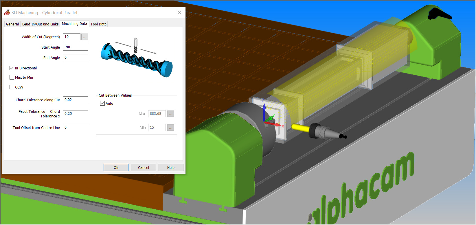
The Cylindrical Parallel strategy for 3D machining has been improved to give easier control over the start/end Angles and CW/CCW direction. The start angle can be less or greater than the end angle, and the CW checkbox now dynamically updates the on-screen cutting area, providing graphical feedback on the area to be cut, and the tool's starting position.
"This simplifies toolpath creation by letting the user specify any combination of angles, and gives an appropriate graphical feedback on the machining area," he said.
Two items of enhanced functionality which are specifically for Alphacam's Lathe module are an update to machining dialogs and new cycles added to C/L Drilling and Tapping.
On the machining dialogs update, turning dialogs now use the new machining dialogs style. Following the improvement in the milling C-axis machining dialogs, the turning dialogs have all been updated and modernized, containing images and tooltips, which improve ease of use.
Additionally, for C/L Drilling and Tapping, the commands have been combined and a new cycle added for pecking, boring, and chamfering. This brings the center-line drilling functionality close to matching the C-Y axis drilling functions, and means that all drilling options are available, which could previously only be used in C-axis and C/L drilling.
Alphacam 2018 R1 contains two major enhancements for stone companies.
Firstly, there is increased support for the Guard visualization when creating disk-cutting toolpath, improving the Geometry Disk Cutting and Surface Disk Cutting cycles. The Guard can also be visualized when selecting elements in layer mapping and changing tools during an operation, along with selecting toolpath elements from the layers tab.
Ferrary says this helps users to graphically see the disk guard when creating toolpath, and how the guard will be orientated during cutting.
The second enhancement is a new option for including extra passes at profile walls when roughing in the Cut with Disk operation. "These extra passes can be set irrespective of the specified width of cut, and ensures excessive stock is removed from the profile walls for finishing.
"It means users no longer have to create an extra operation or define a small width of cut to remove unwanted stock at the walls," he said.


