CAM v14 Software
CAM v14 Software
NCG CAM Solutions Ltd. UK officially released NCG CAM v14 on 23 March 2015.
NCG CAM Solutions Ltd. UK officially released NCG CAM v14 on 23 March 2015. This major release includes a number of new features including UV surface machining, the ability to cover pockets, tools to align 3+2 axis, ability to quickly change the background colour, enhancements to translucency, 5-axis along curve machining, tool axis alignment curves for 5-axis along curve strategy as well as many enhancements including improved automation of the drilling in macros, the ability to copy and paste all of the strategy parameters and the ability to do rest finishing using a toroidal reference cutter.
In NCG CAM v14, UV surface machining is a new feature. This new feature will allow the user to select either a single surface, or a series of appropriate adjacent surfaces, and then to generate machining passes using the selected surfaces and the underlying UV direction parameterisation. This can be done by either a given number of passes, or a step-over distance.
This is not totally automated at this stage and requires the user to investigate the UV surface parameters with a view to swapping them to align them to a common machining direction. The UV directions are indicated by arrows.
New functionality to cover pockets is now available to allow the user to create planar patches from curves, machining passes, or remaining passes.
Creating planar patches from the highest inaccessible passes in a Roughing Toolpath will cover and protect pockets of remaining stock, preventing smaller cutters falling into unmachined regions.
New tools are now available to help the user to align 3+2 Axis boundary planes. Boundary alignment is a particular problem when there is not a planar surface with a suitable normal to orientate from.
The user is now able to quickly change the 'Background Colour' by either using the Drop-down Menu, or clicking the 'Right' button on the mouse. Previously 6 mouse clicks were needed to change it, via the Tools Options page.
With the surfaces displayed in Shaded mode, it is now possible to change the translucency of all surfaces. One use for this is to enable the user to see the holes inside the part when drilling.
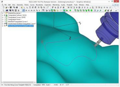
A new feature has been added to the 5-axis module, 5-axis along curve machining. This will allow the cutter to follow a given curve, and the tool axis will remain normal to the underlying surfaces. One example of the use of this feature is to cut windows or trim profiles and edges into components made of composite materials.
Tool axis alignment curves for 5-Axis along curve strategy is a new feature that will allow the cutter to follow a Curve, then a second folder containing additional direction vectors will determine the tool axis. When machining, the tool axis will gradually tilt through these vectors, as it follows the curve.
Many other enhancements have also been added in NCG CAM v14, including improved automation to the drilling macros to make it possible to setup Macros to define drilling canned cycles and make them 'Data Independent' in the same way that milling operations can be setup as Boundary independent by selecting new Boundaries. Also the ability to copy all the strategy parameters from the dialog page to the copy buffer, which will allow the user to be able to paste the copied parameters into a similar dialog in another NCG CAM session, reducing programming time and errors.
In NCG CAM v13 it was possible to machine material that has not been removed by a previous cutter, for example, from the internal corners of the job using Rest Finishing passes. However, the previous, or reference cutter, must be a ball nose type. This enhancement in NCG CAM v14 now allows the reference cutter to be of a toroidal specification.