Hexalobe Tools for Machining Medical Screws
Hexalobe Tools for Machining Medical Screws
A drill, a milling cutter, an ultimate machining strategy with perfectly tuned parameters; this is needed, when machining medical screws made from titanium or stainless steels. Mikron Tool developed a turnkey solution, which simultaneously does the machining of hex lobular bone screws (better known as Torx) 50% faster, guaranteeing also a high degree of precision of the profile and achieving nearly burr-free results.

A drill, a milling cutter, an ultimate machining strategy with perfectly tuned parameters; this is needed, when machining medical screws made from titanium or stainless steel. Mikron Tool developed a turnkey solution, which simultaneously does the machining of hex lobular bone screws (better known as Torx) 50% faster, guaranteeing also a high degree of precision of the profile and achieving nearly burr-free results.
With an increasing tendency, yearly 900 million medical screws are produced. Each second which can be gained in the process counts. Most of these screws are produced on lathe machines, on the main spindle the thread and on the subspindle the hexalobular Torx socket is machined. That particular operation is usually slower and defines the cycle time. Here is an opportunity to improve the efficiency, all be it by only a few seconds. Nevertheless it saves the manufacturer time and money.
Mikron Tool offers with the Hexalobe-Program a turnkey solution, which is not only based on the cutting tools, but also delivers a package with the best machining strategy and the right parameters. Because during the development of the program it became quite clear that good results can only be obtained when all factors fall in place correctly.
The two materials with which today 90% of all medical screws are made are titanium and stainless steel. These are quite different when it comes to their behavior during the chip-removal process. Such that during the development it became clear that the tools as well as the suitable strategy needed a differentiation. Especially with titanium with its high elasticity stronger cutting force was required, which in turn produced higher stress on the cutting edges. This already meant right from the beginning of the development, that a different carbide was called for.
For the machining process, both materials have to be differentiated. While with titanium the helical interpolation and also side milling are possible, Mikron Tool only recommends side milling when working with stainless steel. Even though this particular process is a bit more time consuming.
A well-defined strategy was just as important as the cutting tools when development was initiated. Because when choosing the tools it must be clear how these are being applied.
Right from the beginning different approaches were considered. Especially efficient turned out to be the one that could do with a minimum of different tools, i.e. Step drilling – milling the hexalobe – subsequent deburring.
Other strategies like predrilling of the six exterior diameters and the center with the following milling and deburring were a challenge, especially when working with titanium. It turned out to be a demanding task for the microdrills.
The milling process, in the chosen strategy the most time consuming operation, can be done with helical interpolation (with max. pitch 0.8 x d) or with side milling (with stepover max. 0.5 x d).
Each procedure has its pros and cons: With helical interpolation there will be a slight lateral load at the milling cutter (Fx), since there is also a simultaneous vertical stress (Fz).
A higher stress on the cutting edge corners has to be reckoned with and because of this they were geometrically reinforced. Generally this produces a faster and more fluid operation. With the side milling (or wall milling) the total depth is reached in several steps, since only two axes are used for each step. The step-over stays the same for the entire operation even though the radial stress on the cutter is more elevated.
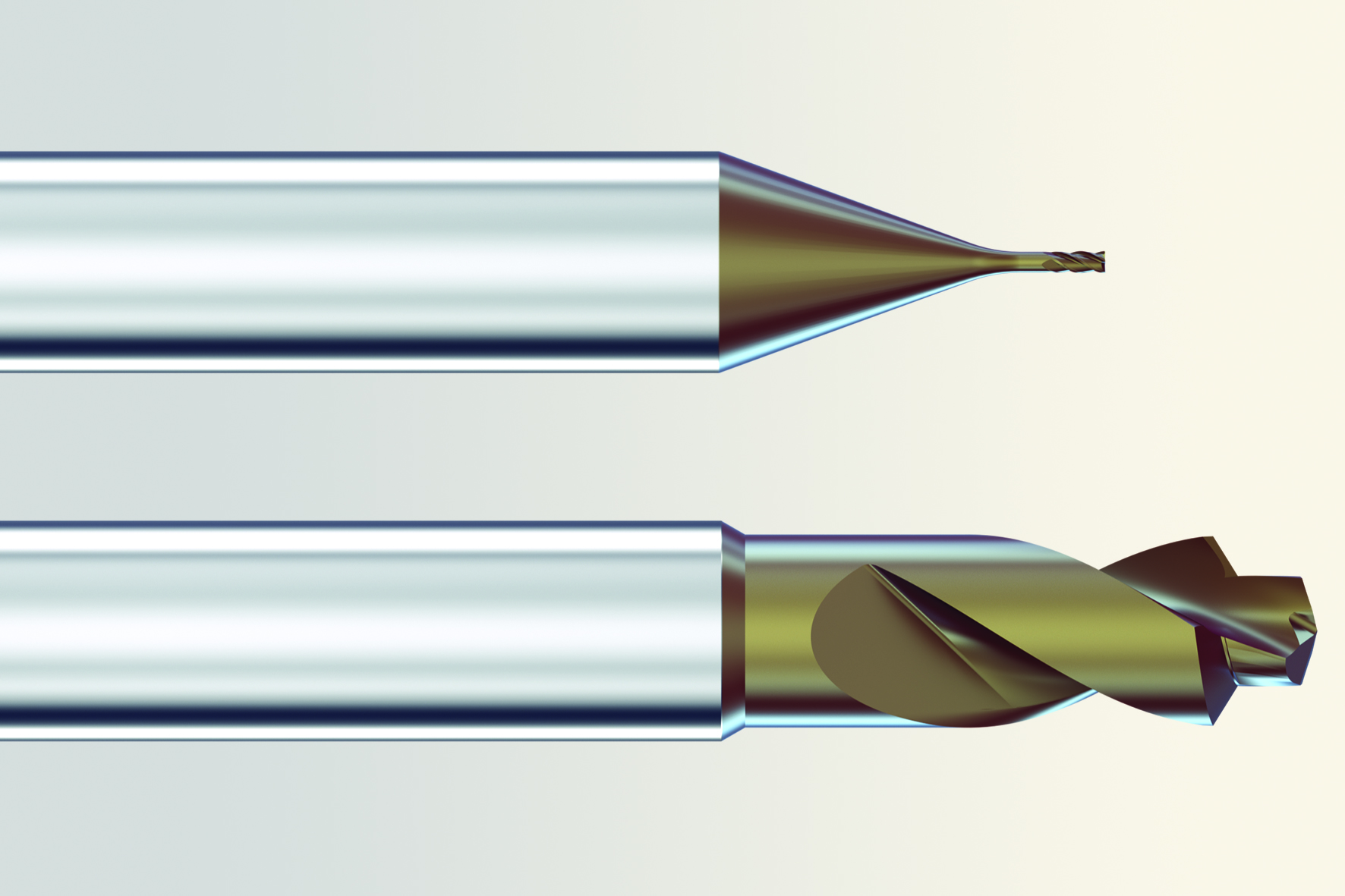
The four operations (pre-hole drilling – chamfering – milling – deburring) need to be completed in three operations with two tools. First a step drill does the center bore and a chamfer of 120 degrees and this right away with an excellent surface quality of Ra 0.2 um, Rz 0.8 um. After the milling of the final shape, this tool will be used once again in the last operation to achieve a nearly burr-free surface and superior surface quality. The milling cutter with 3 or 4 flutes – depending on diameter – is available in two standard lengths, so that depending of the screw type, different Torx shapes can be machined. It's high stiffness allows machining with high feeds and massive stepover, while still guaranteeing the necessary hexalobular profile accuracy. The surface quality is given by the special geometry which also affords to work with high stepover so that the operation can be completed with few steps.
Besides efficient machining, which means short cycle time and long tool life, the development of the new tools concentrated also on achieving top quality. Tight tolerances must be kept to guarantee profile accuracy and wall squareness of the hexalobular socket, and this from the first to the last screw produced.
Obviously the surface quality and burr condition are also an important topic.
The head of development, Alberto Gotti, confirms that there is no "perfect solution for all cases."
Even though, this turnkey program with a combination of cutting tools, recommendations for the strategy and parameters gives the end-user excellent support, he still challenged to find "his" balance between most efficient machining, high precision and quality.
First experiences with the new CrazyDrill and CrazyMill Hexalobe tools on a lathe machine 32/8 from DMG Mori have shown, that cycle time compared to other on the market available tools could be reduced by 50% to 60% while at the same time with a fast feed (0.03mm/rev. per flute) and high surface quality (Ra = 0.2 um) can be reached.


