hyperMILL ShopViewer Visualization Solution
hyperMILL ShopViewer Visualization Solution
OPEN MIND Technologies AG has released hyperMILL ShopViewer, a proprietary visualization solution for the workshop.
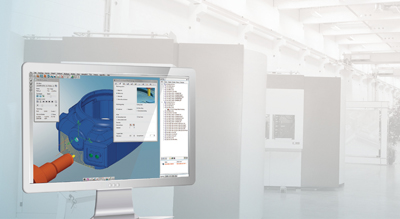
OPEN MIND Technologies AG has released hyperMILL ShopViewer, a proprietary visualization solution for the workshop. It provides machine operators with a complete overview of the upcoming NC program right through to simulation and ensures that only safe, checked NC programs run on the machine.
Although the digital process chain from design through NC programming already exists in many companies, there is often a break in the chain when it comes to the production environment. The actual programs are forwarded to the controller via the network, but the associated information is not normally transferred. The machine operator can usually only take advantage of static aids like drawings, tool reports, screenshots, PDFs etc. It is a different picture with a viewing system. Here, the system provides the specialist operating the machine with all of the information related to manufacturing data, as well as geometry and component structure.
ShopViewer makes it possible to view and examine data from hyperMILL and hyperCAD-S in more detail directly next to the machine. "The viewer typically allows the machine operator to view everything but not modify anything," explains Wolfgang Weiss, product manager for CAD at OPEN MIND.
hyperMILL ShopViewer was developed specifically to the requirements of hyperMILL users. The information visible on the hyperMILL ShopViewer workspace includes:
• 3D model with the ability to measure features CAM program
• 3D clamping plans
• Tool data
This way, the machine operator can simulate the actual manufacturing process and gain a better understanding of the milling process in the machine. The hyperMILL operating concept allows users to work in their usual interface, which enables them to reach their goals quickly. "hyperMILL ShopViewer features an uncluttered interface, where the user can only see what he or she needs at any given time," says Weiss.


