NCG CAM v16.0
NCG CAM v16.0
NCG CAM Solutions Ltd. UK officially released NCG CAM v16.0. This major release includes a number of new features including Selected Surface Machining for Waterline Passes, Combined Passes for Waterline & Constant Stepover, Tangential Extension for Raster Passes, 5-Axis Flank Machining, as well as many new user interface features and enhancements.

NCG CAM Solutions Ltd. UK officially released NCG CAM v16.0. This major release includes a number of new features including Selected Surface Machining for Waterline Passes, Combined Passes for Waterline & Constant Stepover, Tangential Extension for Raster Passes, 5-Axis Flank Machining, as well as many new user interface features and enhancements.
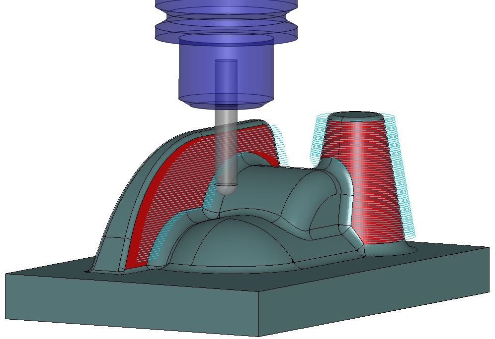
In NCG CAM v16.0, a new feature had been added to extend the ability of the 'Machine Selected Surfaces' to include Waterline passes. This new feature in NCG CAM v16.0 extends the ability of the 'Machine Selected Surfaces' to include Waterline passes. This provides the ability to machine up to the surface edges without the need to create a boundary, in the same way as can be selected for the Shallow strategies, Raster, Radial and Spiral.
A new routine is now available that allows the creation of Waterline Passes between the upper angle of 90° down to a specified lower angle. Constant Stepover Passes are then created to 'fill in' the shallow areas between the specified lower angle and 0°. Linking is a single operation from the top down, so that the linking order is a combination of waterline, constant stepover, waterline, etc. This strategy will give a smoother finish because it allows the machining to be done in a single operation, avoiding the problem of cutter wear.
Another new feature in NCG CAM v16.0 allows Hole Plans in the Tree View to be "Tagged" and identified with a coloured marker if they have previously been used to generate drilling cycles. This visual difference makes it easier to identify the remaining holes that require machining.
In previous software versions, extending raster passes, would allow the cutter to roll over the edge. A new extension option creates passes that are extended at a tangent to the ends of the existing passes and therefore extend the path beyond and away from the material being cut. The result of this is that sharper edges are maintained. A horizontal pass extension has also been added.
A new feature has been added to give the ability to trim the passes back by a small amount, which will eliminate any slight marking that could potentially be left on vertical walls immediately in front of the passes.
A new feature to calculate the cutting direction vector using 2 mouse clicks that snap to the wire frame model to determine the angle, is now available. This will save the user time, as currently, if an accurate angle is required, the model must be interrogated manually. While the Passes Dialog is open, the coordinates are recovered from the model in the Graphics Window. The result is then entered into the "Angle" field in the dialog.
The basic style of the user interface has remained unchanged since this CAM software was first produced. Modernising various aspects of the interface is in the process of being addressed and will be rolled out in NCG CAM v16 point releases.
Improvements in NCG CAM v16 will include:
- Better handling and positioning of the Toolbars when the graphics window is narrow.
- The ability to dock the Process Manager.
The aim is to make the user interface better and easier to use, not just different.
In NCG CAM v16.0 is now possible to specify the cutters overall length value in the Tool Database; E.g: The value that is usually referred to as "L1" in a tooling catalogue. The "Body Length" value is the "Usable body length" of the cutter. E.g: The part that is exposed from the Holder.
A Recycle folder has been added to the Directory Tree View for deleted items. This allows the user to Choose and Restore specific items, if required.
Cutting parameters that have been set are now retained when transforming a parametrised toolpath.
Previously, the Transformed Toolpath folder was presented in the directory view; the properties of this were the details of the transformation. This new toolpath has its' parameter values reintroduced. This new action saves the user time spent doing this manually.
Flank Machining is a 5-axis simultaneous milling process that can be used typically for fluid parts in turbo-engines, aeronautical applications, turbine and impeller blades and is available in NCG CAM v16. Using the whole flute length of the cutting tool, the aim is to machine the part surface in only one cut.
Roughing and finishing cycles are now available, together with automatic linking and tilting.
Another new feature which will soon follow in an NCG CAM v16 point release will provide support for barrel-type cutters when using the 5-axis machining routines. The defining feature of a barrel cutter is the "circle-segment" radius; this allows a much greater area of engagement between the cutter and workpiece when compared to a typical ballnose tool. This larger engagement area allows the use of larger step-over values, while still maintaining surface finish. Metal-removal rates are also expected to be improved when using barrel cutters and less cutter wear when compared to a typical ballnose tool.


