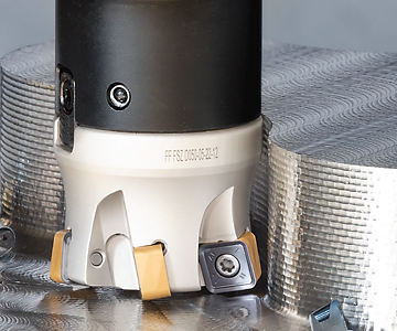
Neofeed Cutters
Neofeed Cutters
When mounted in a NEOFEED tool, the insert enables a positive tool rake angle which assures smooth cutting and reduced cutting forces and power consumption. The insert pocket has a dovetail shape that provides rigid and reliable insert clamping and improves the a cutter's capability to withstand heavy load. These features provide increased cutting data for better productivity and for improved tool life.

The new NEOFEED cutters are available in the diameter range 2.00"-4.00" in the following two shell-mill design configurations:
- FFQ8 -12 with 12° cutting edge angle for extremely high feed per tooth (fast feed milling) at depths of cut up of to .059".
- MFQ8 -12 with 22° cutting edge angle for milling with "moderate" feed milling (less than high but much more than common) at depths of cut up of to .118".
- When milling near a wall using MFQ8 D...-12 cutter up-milling is recommended.
The new shell mills carry the same double-sided square inserts FFQ8 SZMU 120520… with 8 cutting edges.
When mounted in a NEOFEED tool, the insert enables a positive tool rake angle which assures smooth cutting and reduced cutting forces and power consumption. The insert pocket has a dovetail shape that provides rigid and reliable insert clamping and improves the a cutter's capability to withstand heavy load. These features provide increased cutting data for better productivity and for improved tool life.
The new FFQ8/MFQ8 D…-12 shell mill cutters feature a fine-pitch option for 2.00 - 4.00" cutters. This feature extends the range of application options for roughing specifically in the Die & Mold, Aerospace and general engineering industries.
FFQ8 SZMU 120520… Insert Features
- Double-sided square insert with 8 cutting edges.
- High-strength body structure.
- The specially designed .0787" radius insert corner with reinforced cutting edge increases insert strength when milling near a wall.
- Available with two types of cutting geometries (T/HP) for optimal machining different materials.
- FFQ8 SZMU 120520... inserts are produced from ISCAR's latest carbide grades with post-coating treatment technologies that guarantee greater tool life and higher productivity.
- The same insert fits the both types of the new cutters.
- An attractive economical solution due to insert cost effectiveness per one cutting edge.
FFQ8 SZMU 120520T - for steel, ferritic and martensitic stainless steel, cast iron and hardened steel (ISO P, K and H groups of application).
FFQ8 SZMU 120520HP - for austenitic stainless steel and high temperature alloys (ISO M and S groups of application).
FFQ8/MFQ8 D…-12 Cutter Features
- FFQ8/MFQ8 D…-12 A fine-pitch design for increased metal removal rates.
- Coolant holes directed to each cutting edge, for efficient coolant and improved productivity.
- Protective coating of a cutter's body provides better chip flow and protection from corrosion and wear.
Cutting data
The recommended cutting data are shown in the tables in the last pages.
NEOFEED
An advantageous tool for productive and cost-efficient rough milling
FFQ8-12
Fast Feed Face Mills Carrying Double-Sided Inserts with 8 Cutting Edges
• Radius for programming .142"
• To generate a straight surface without cusps, the width of cut most not exceed DC
• For slot milling or machining with high tool overhang, the maximum depth of cut should be reduced by 30%
(1) Cutting diameter maximum
(2) Number of inserts
(3) Maximum ramping angle
(4) For interpolation
(5) For interpolation
(6) Master insert identification
MFQ8-12
Moderate Feed Face Mills Carrying Double-Sided Inserts with 8 Cutting Edges
• Radius for programming .197"
• To generate a straight surface without cusps, the width of cut most not exceed DC
• For slot milling or machining with high tool overhang, the maximum depth of cut should be reduced by 30%.
(1) Cutting diameter maximum
(2) Number of inserts
(3) Master insert identification
FFQ8 SZMU
Square Double-Sided Inserts with 8 Cutting Edges for High Feed Milling
• For side plunging, the initial cutting feed is 0.1 mm/t
• T- for steel, ferritic and martensitic stainless steel, cast iron and hardened steel
• HP - for austenitic stainless steel and high temperature alloys.
Averaged cutting data for FFQ8 fast feed cutters
* ISCAR material group in accordance with VDI 3323 standard
** Quenched and tempered
For machining in unstable conditions, the recommended cutting data should be reduced by 20-30%.


