New Nesting Engine in Alphacam 2018 R2 Software
New Nesting Engine in Alphacam 2018 R2 Software
Tests on the new nesting engine unveiled in Alphacam 2018 R2, by Vero Software, show a 17 percent improvement in material yield. Using proprietary technology to deliver what Brand Manger Hector Henry says are "best-in-class geometry," toolpath optimization and part handling, the nesting engine also provides faster calculation times, along with improved feedback and graphics.
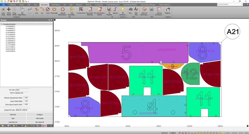
Tests on the new nesting engine unveiled in Alphacam 2018 R2, by Vero Software, show a 17 percent improvement in material yield. Using proprietary technology to deliver what Brand Manger Hector Henry says are "best-in-class geometry," toolpath optimization and part handling, the nesting engine also provides faster calculation times, along with improved feedback and graphics.
The overall theme of the latest release, Henry adds, is to save time and improve productivity.
Parametric Rules have now been migrated to C# and have an enhanced GUI and functionality, allowing for greater control, improved UX and simpler, more streamlined, logic statements, which he says has improved productivity and reliability.
The Face Milling Cycle has been enhanced, and is now part of Alphacam's Core Functionality, creating intelligent toolpaths, allowing users to face (surface) mill irregular and multiple geometries. "This improves productivity, as the user doesn't need to create several operations to achieve the same result," he said.
Productivity has also been improved through the new Order by Intersecting Geometry function, which saves significant time when ordering the sequence of a complex job. It works by letting the user select a previously created geometry to define the order of geometries or toolpaths, based on those that intersect the selected geometry first.
The Parametric Sketcher is now considerably more powerful, thanks to an updated UI, meaning the window can be resized. This provides greater visibility over the Parameters and Actions list, which will be essential for managing complex projects. There are also improvements to the Sketcher's geometry creation tools for creating fillets and chamfers as part of the Geometry creation tool set. This improves productivity, as it does away with the need to calculate those points.
Enhancements to Alphacam's dimensioning system provide greater clarity when printing and presenting information. User-defined suffixes for both the primary and alternate units – as well as a scale factor – mean that two separate values can now be displayed.
Importing CAD models has been updated through the support of SOLIDWORKS configurations. "Alphacam now has a new interface for users to select which configuration of an assembly to import, without the need to ascertain that the last version saved in SOLIDWORKS matches the one they want," Henry says.


