NUMroto X
NUMroto X
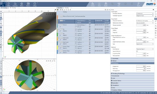
NUMroto X breaks new ground in the definition and organization of probing cycles. These can now be recorded in sequences, analogous to grinding operations. In this way, the various probing processes can be clearly displayed and set up by the user. Any number of sequences can be created for the same tool, containing grinding operations, probing and dressing cycles, or both. With the ability to execute other sequences from within sequences, they can be combined in any way, allowing complex manufacturing sequences to be configured while remaining clearly displayed.

With NUMroto X, NUMROTO introduces a new product line that will complement and successively replace the existing software package.
NUMroto X has been rewritten from the ground up, with special attention paid to using the most modern approaches and up-to-date technologies. This allows for the implementation of demanding requirements for tool grinding and enables the use of the latest possibilities and functions of modern computer systems. After NUMROTO DOS and NUMROTOplus, a new chapter is being opened with NUMroto X, which will provide our customers with the usual high standards of NUMROTO technology in the long term.
Like the existing solution NUMROTOplus, NUMroto X is also designed as a desktop application and will be available in the same version for use on both the grinding machine and the workstation computer. Proven concepts such as a multi-user database, process analysis with NUMROTO-3D, and product documentation using NUMROTOdraw will continue to exist with NUMroto X.
During the development of NUMroto X, various innovative development focuses were implemented. Instead of nested dialogs, the user interface relies on scrollable areas that clearly display the numerous parameters. User inputs are immediately evaluated and converted into machining paths, allowing for fast workpiece visualization. This makes it possible to observe the effects of parameter changes in real time. For this purpose, the novel visualization calculates a pixel-precise image for each zoom level, making every detail visible, no matter how small.
NUMroto X breaks new ground in the definition and organization of probing cycles. These can now be recorded in sequences, analogous to grinding operations. In this way, the various probing processes can be clearly displayed and set up by the user. Any number of sequences can be created for the same tool, containing grinding operations, probing and dressing cycles, or both. With the ability to execute other sequences from within sequences, they can be combined in any way, allowing complex manufacturing sequences to be configured while remaining clearly displayed.
For the calculation of machine movements, the kinematics module was implemented with a completely new approach. It offers interesting possibilities, including support for interpolating 6-axis movements. New strategies have been implemented for the transfer movement between two grinding processes, which are not only more efficient but also control the axes more optimally.
When creating a new workpiece, the user is supported by an extensive default value system. If required, the default values can be configured almost arbitrarily by the user himself and adapted to the properties of the tool pallet to be produced.
NUMroto X in its first version will provide the range of functions for the production of complex standard milling cutters. There is a large selection of templates for face, shell, and corner profiles that can be combined as desired to form a tool profile. Just as flexible are the combination of shell cutter, face cutter, and clearance definitions.
Even if NUMroto X does not initially match the functional scope of NUMROTOplus, the new software package boasts the latest functions and innovative solutions. It is important to us to continue supplying our customers with the proven and high-quality NUMROTO technology, which is why NUMROTOplus and NUMroto X will be available in parallel for several years.


