Surfcam 2019 R1 Software
Surfcam 2019 R1 Software
Responding to the increase in hybrid manufacturing, the latest release of Surfcam introduces a new Additive Machining module. Supporting the Direct Energy Deposition method, Surfcam now offers a dedicated manufacturing cycle which accurately guides a laser as it deposits material to form a shape. After that, the shape is machined using Surfcam's milling cycles to create the final component.
Responding to the increase in hybrid manufacturing, the latest release of Surfcam introduces a new additive machining module. Supporting the Direct Energy Deposition method, Surfcam now offers a dedicated manufacturing cycle which accurately guides a laser as it deposits material to form a shape. After that, the shape is machined using Surfcam's milling cycles to create the final component.
As Surfcam 2019 R1 now offers full ToolStore support for additive manufacturing, shapes can be built using almost any milling cycle, including advanced functions such as rotary and 5-axis simultaneous machining.
Surfcam Brand Manager John Buehler says the new Additive Lace cycle is designed to construct geometry on a layer-by-layer basis, depositing a continuous molten bead of material which adheres to the parent material.
"Using the same intuitive dialog interface as all other Surfcam cycles, Additive Lace not only offers the ability to work with various CAD entities, but also empowers the user to determine numerous control types, such as lace angle, amount of finish passes, and undercut mode," he says.
In total, Surfcam 2019 R1 includes around 30 individual enhancements.
Mindful of the need to generate quick toolpaths to reduce production costs, Surfcam 2019 R1 introduces three performance-boosting enhancements to its machining engine, benefiting both turning and milling operations.
Regeneration time has been reduced by around 20 percent when editing the Move Angular/Index commands.
"Responding to customer feedback, the Waveform machining algorithm has been enhanced to reduce processing time. Previously, performance bottlenecks were detected when small stepovers were used, or on components with narrow channels and heavily curved regions. Manufacturers will now notice average time savings ranging between 15 and 60 percent, depending on the complexity of the component and its cycle parameters," Buehler says.
And, due to improvements in the way Surfcam's machining engine generates data, machining large complex components is now considerably quicker. This has been achieved by the way the software calculates prismatic geometry within the toolpath.
A new Parting Off cycle is available for turning customers, satisfying a high demand for a single cycle to not only perform the parting off toolpath, but also to deburr the back edge during the operation. "Like all other turning cycles, Parting Off offers extended help through dialog pictures, and is sensitive to the current stock position," Buehler says.
Again, for turning customers, a new Up-Cutting function has been added to the Finish turning cycle. This enables high productivity finishing to be achieved in conjunction with Sandvik Coromant's CoroTurn Prime tools and inserts.
Located alongside the Down-Cut modifier, Up-Cutting reverses the direction of the toolpath to utilize the Prime insert geometry. Also, the cycle feedrate can be expressed using the "Chip Thickness" modifier, as well as in the traditional format of feed per revolution.
Found in the Rough Turn cycle, the Stock Runout function has been enhanced to give greater toolpath control when exiting the cut. The inclusion of Runout Angle and Runout Length means toolpaths can be trimmed to user-specific demands.
"Both the Thread Turning and Finish Groove cycles now benefit from functionality found in other turning commands. Safe Distance modifier has been added to the Thread Turning cycles, giving more accurate control at the start position of a threading toolpath," says Buehler. "Finish Groove toolpaths can be more tightly controlled with new Start and End Extension modifiers."
The Spindle Set-up function for multiple-spindle lathes now includes main and sub spindle C angle positions, further guaranteeing no collisions during the parts transfer command.
Buehler says that although Surfcam Inspect is less than two years old, it continues to grow fast, and Surfcam 2019 R1 introduces 13 new enhancements to it. "Firstly, the mathematical brain behind the product is being switched to use the PCDMIS fit libraries supplied by our parent company, Hexagon. All Geometry Fit calculations, such as measurement deviations and GD&T values, now use a higher level of certified and approved algorithms.
"And we've introduced more customization. In the past, users had to accept the standard Measurement Report, but now they can develop their own software plugins to personalize it, along with developing their own probing Canned Cycles, usually in Renishaw or M&H format."
Probing features can be managed more easily, as all commands are automatically created on separate layers. "Also, where either the solid model geometry is incorrect, or the model isn't available, the new manual feature means it's still possible to inspect a region," he adds.
Through user feedback, specific probing features now work with rotary solid faces, and the feedback can also include evaluation of axis deflection.
"The final enhancement to this area provides two new output variations in the Work Offset function: Type, and Axes. These give greater control and a more detailed inspection routine, while communicating to the machine tool via the NC Gateway," Buehler says.
The Hole Cycle now has additional collision checking. While stringent detection has been in place for a number of releases – such as a toolpath being re-directed to avoid a clamp – Surfcam 2019 R1 now checks if a hole is obstructed by any part of a fixture. Where such a collision exists, the system removes the drill position and alerts the user.
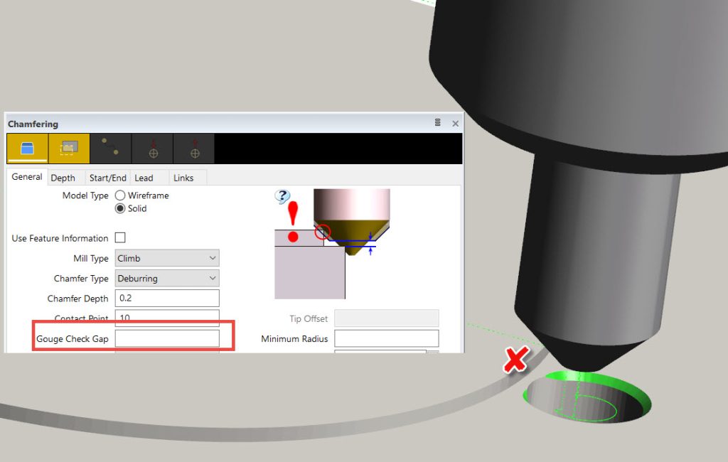
Gouge Check Gap has been added to the Chamfering Cycle to give even stricter control over the toolpath. Specifically, neighboring features which could potentially come into contact with the flute of the taper tool can now be excluded.
Surfcam 2019 R1 supports the latest version of all CAD files. "Focusing on a few formats, users will notice, for instance, support for SpaceClaim 19 (ACIS V28), Parasolid version 30.1.247, Inventor 2019, and Creo 5.0. All other CAD formats will be catered for when a newer version becomes available," Buehler says. "It's particularly exciting that, regardless of which license a user has, they'll be able to load all Designer files – *.v_t and *.vdf extensions. Designer is Vero Software's latest CAD package, featuring direct modelling technology. This will be a major boost for manufacturers who haven't yet sampled the power of Surfcam's Solid Machinist capabilities."
Concluding, Buehler says: "Overall, there are more than 30 individual enhancements in Surfcam 2019 R1, geared towards improving efficiency, productivity, and ease of use, to keep manufacturers ahead of the game with the best technology available."


