SURFCAM 2020.1 CAM Software
SURFCAM 2020.1 CAM Software
The latest release of SURFCAM features toolpath associativity for the facemill cycle, the option to extend the solution's parallel lace toolpath, enhanced additive undercutting, and a total of about 30 updates. Alongside the new SURFCAM 2020.1, the optional CAD for CAM Designer module has now replaced Part Modeler.

The latest release of SURFCAM features toolpath associativity for the facemill cycle, the option to extend the solution's parallel lace toolpath, enhanced additive undercutting, and a total of about 30 updates. Alongside the new SURFCAM 2020.1, the optional CAD for CAM Designer module has now replaced Part Modeler. From model design to part repair and modification, SURFCAM Designer is said to be an ideal solution for taking geometry through to manufacture.
More than 50 enhancements have been made to Designer, including the ability to attach finishing and tolerance information to models and faces with the new "surface attributes" command. SURFCAM reads this information and applies it to the features, so it can be used in strategy decisions, or to set speed and feed rates.
Additionally, this latest version offers the powerful new "edit boundary" command for modifying the trimming of faces directly on a sheet or solid body without having to extract any surfaces or edges. It also delivers a fresh new look and feel for the "auto-constrained surface" command, used to quickly create complex surfaces.
SURFCAM 2020.1 enhances the additive lace cycle's "undercut" function by allowing the user to set a maximum overhang angle. Product Manager John Buehler says, "This is necessary because different materials and processes require different negative material build-up, depending on the target shape. If the undercut angle is too big, it can be compensated for by using the maximum overhang angle, effectively over-ruling the angle on the part."
Additionally, further boundary control options have been included, which mimic the same functionality of other milling cycles, allowing for greater material displacement control.
The new release significantly enhances the existing SURFCAM chamfering cycle with five new pieces of functionality, which are similar to those already found in the profiling cycle. Greater toolpath control is achieved with the new cut increment and Z-offset modifiers. "Previously, if there were heavy cutting conditions, several chamfer cycles would have to be created. Now, users simply set a cut increment value, which not only results in multiple toolpath passes, but also increases tool life," Buehler says.
Six "corner strategies" have been added, enabling programmers to choose the type of external corner condition the cycle produces. This is particularly useful when a smoother corner blend is required.
The introduction of "optimize path and lace bandwidth" modifiers reduces cycle time by determining the order in which the cycle is deployed.
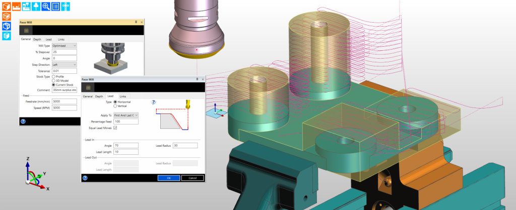
"Toolpath associativity is a vital factor when programming production components, as CAD modifications can take considerable time," Buehler says. "SURFCAM 2020.1 removes such delays by making the facemill cycle sensitive to the stock model. When either the stock or component solid model are altered, the toolpath automatically adjusts both the X-Y and the Z height of the toolpath."
Secondly, the lead modifier now helps increase tool life with a "horizontal" lead type, which "rolls" the cutter into the initial face of the material, reducing cutting forces.
While the "prefinish plunge" function in previous versions of the software reduced cycle times, this increased the potential for collisions, where the stock was larger than the groove feature. The new release resolves that issue by introducing a "use current stock" function, ensuring the cycle always begins higher than the current stock.
The toolpath in the parallel lace cycle can now be extended. The function is similar to the one in the profiling cycle, which has been brought in following requests from users. "The extensions follow the direction of the cut, and are applied in the primary direction, 'stretching' the toolpath, which guarantees better surface texture, an allows the cycle to cater for over-size stock," Buehler says.
An enhancement to the existing "swarf" control command means a specific time period, in minutes, can be set, for the turning insert to be in contact with the material. Buehler says this will be particularly useful when machining hard material where there's a requirement to control the wear rate on the insert. "The tool will return to its retract position once the time period has been reached. SURFCAM will automatically put stop commands into the program, allowing the user to inspect the insert before continuing with the rest of the cut."
The Tombstone Manager has evolved into a particularly powerful tool for production engineers working with multiple batch quantities. This latest release introduces two significant enhancements controlling the deployment of each tool, with two new "priority" functions.
Firstly, "by tool then by plane" rationalizes by tool, followed by reducing indexes. Secondly, "by plane then by tool" rationalizes by plane/datum before reducing tool changes. "Anyone wanting to use part files with multiple machining sequences will see that the general performance of the tombstone software has improved, and that sorting priorities have been enhanced," Buehler says.
SURFCAM 2020.1 now fully supports turrets with half positions. This is where the turret has numbered positions like a clock face, with a further set between the main positions. "Typically, a 24-station turret is numbered in this sequence: 1, 13, 2, 14, 3, 15, etc. The simulator now displays all the tooling in its correct relative positions, giving a realistic simulation. This can be particularly important when neighboring tools get close to the stock and part," Buehler says.


