Version 4.0 Release 3 CAD/CAM Software
Version 4.0 Release 3 CAD/CAM Software
Tebis America has announced the release of its Version 4.0 Release 3 software. The highlights of the new launch include: toolbars and menu panels that can be easily docked to the edge of the application window; software interface that allows a user to learn to operate it more quickly and easily and with less effort; and a new project dialog with the most recently used files is displayed immediately after the program is started.

Tebis America has announced the release of its Version 4.0 Release 3 software. The highlights of the new launch include: toolbars and menu panels that can be easily docked to the edge of the application window; software interface that allows a user to learn to operate it more quickly and easily and with less effort; and a new project dialog with the most recently used files is displayed immediately after the program is started.
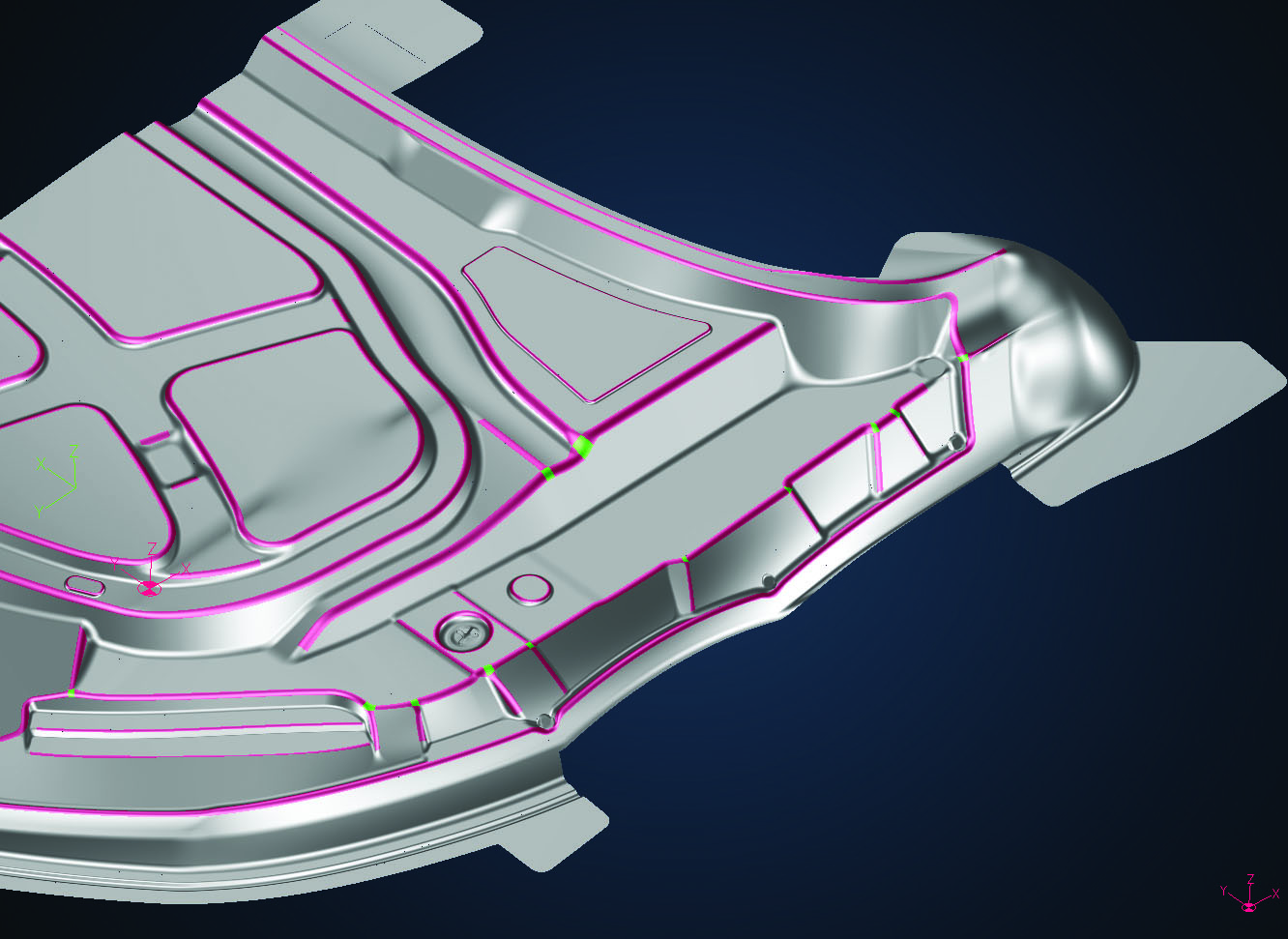
With Version 4.0 Release 3, Tebis has also improved the display of wire-frame models and isolines. The user is often confronted with the problem of many isolines, which can make the view of the components unclear on the screen. Further, Tebis has focused on a more efficient use of time by automatically breaking up assemblies and complex files into multiple individual files.
Another time-savings benefit is optimized reverse engineering. Release 3 provides improved algorithms that generate perfect transitions for 4-edge surfaces. The user can also quickly and easily adjust the approximation tolerance as well as control generated radius runouts and theoretical edges more efficiently.
In surface modeling, when generating surfaces with constant curvature, Release 3 supports symmetrical areas and provides better management of input parameters when using optimization functions.
The new Version 4.0 Release 3 also delivers customers improved reliability in NC programs. An extended list with known machine conflicts is integrated in the CAD/CAM software for quick access.
The NC automation of 2.5D drilling and milling is also more efficient, because the processing sequence in feature-based NC programming can now be more easily influenced by feature groups. Tool optimization has also been extended in the Job Manager. Tools can be changed across machining operations in NCJobs.
The user can shorten cycle times by roughly 30 percent in laser cutting and trimming because the improved NC point distribution results in more compact programs. The user can set axial tolerances and manually remove NC points. In Release 3, head tilt directions on the manufacturing machines can also be handled more easily in stamping areas. This prevents rapid pivot movements of the machine. Toolpaths can be checked numerically with the "Collision check machine" add-on, so that collisions and limit-switch conflicts never even occur. This also saves time and costs.


