VISI 2018 R1 Software
VISI 2018 R1 Software
The latest release of VISI, from Vero Software, provides a wide variety of new and enhanced items of functionality for both CAD and CAM, specifically for the mold and die market. VISI 2018 R1 introduces a new Mold Tool module based on VISI's Assembly-Ng technology.
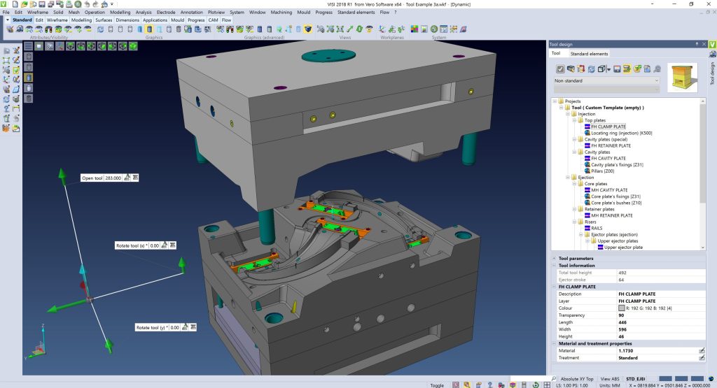
The latest release of VISI, from Vero Software, provides a wide variety of new and enhanced items of functionality for both CAD and CAM, specifically for the mold and die market. VISI 2018 R1 introduces a new Mold Tool module based on VISI's Assembly-Ng technology. This redeveloped module provides greater flexibility when constructing supplier and non-standard tool configurations. Customizable templates, including the management of blank and predrilled plates, allow for easy tool layout creation and enhanced editing at any stage of the design process.
VISI Product Manager Marco Cafasso says: "The new Mold Tool provides a greater level of flexibility for both tool creation and advanced editing. This allows for adjustments to be made at any stage of a tool-designs development. All assembly components are automatically updated when plate adjustments are made, including component cavity manufacturing data."
As part of a wider project of using established and proven Group technology, the Reverse Engineering Suite has been officially released in 2018 R1, allowing for a point cloud to be loaded from an external file, and the optimized mesh created by setting different refining and smoothing options.
The ability to create project design and manufacturing technical reports have been included within the systems snapshot manager using data captured throughout the CAD and CAM project stages.
Further enhancements have been made within the plastic Flow warpage prediction module to improve result accuracy for complex technical polymers. These improvements have been achieved by a complete revision of the algorithms for the Holding phase. Pressure and flow rate calculation adjustments, combined with the new shape solver, significantly improve the performance by reducing the calculation time up to 40 percent.
Sheet-metal developments in the progress strip development area and blank prediction include the ability to manage constraints of specific faces of a blanked component. It is also possible to define the face constraint in X or Y, or in both directions, which is particularly useful for designers who want to blank only specific areas of a model for step-by-step stage unfolding. In addition, the process of managing strip layouts using double component geometry has been enhanced to reduce the development time of a 3D strip design.
CAM developments include faster geometry preparation, and an enhanced 2.5-axis chamfering strategy provides many quality updates, including intelligent approach and retract points, advanced obstacle management, and significant speed improvements.
For 3D waterline milling, new adaptive stepdown capabilities can now manage variable Z steps for each independent area within the same piece being machined.
User interface improvements to the CAM navigator will see the build process status on the operation itself, allowing the process manager to be switched off if required. Tool sheet reports have been updated where the user can benefit from the enhancements to the snapshot manager. In addition, for anyone requiring hole information generated from the feature recognition, there is also the added benefit of exporting the data to csv files for external use.
Finally, sharing process knowledge is key to tracking the digital thread throughout the entire manufacturing process. A new VISI-to-PC-DMIS interface enables PC-DMIS to read the native VISI CAD file directly with annotation and points previously defined in VISI loaded automatically into PC-DMIS to be used for quality-control purposes.


