VISI 2020.1 Mold and Die Software
VISI 2020.1 Mold and Die Software
The latest release of VISI mold and die software enhances the progressive die design processes, along with enhancements for the Reverse module. Upgrades to the new part unfolding technology provides the ability to work directly on the original solid model, supports blanking functionality, and manages parts with non-linear bends.

The latest release of VISI mold and die software enhances the progressive die design processes, along with enhancements for the Reverse module. Upgrades to the new part unfolding technology provides the ability to work directly on the original solid model, supports blanking functionality, and manages parts with non-linear bends.
The sheet-metal part recognition provides an improved graphical representation of the part, analyzed by identifying bends, planar faces and features. Different face types can be set to be considered for the blanking process. The new technology allows linear blank unfolding and flange unfolding to be combined into a single functionality. With linear bends, the system will unfold using the linear bend unfolding technology, while flange areas unfold using the FEA unfolding solution. Coining faces can also be unfolded as part of the same process.
VISI Product Manager Marco Cafasso says the major advantage of the new technology is the associativity provided with the original model during the die design process. "It allows the original part to be modified, and changes to be automatically propagated on the banked part. This new feature allows all the linked parts to be rebuilt in reference to a modification done to the original part. This is extremely useful because it updates all the studied parts in a single click, and is a major time saving in the design and modification phase of a progressive die."
VISI 2020.1 also provides a direct interface to Stampack Xpress for die simulation.
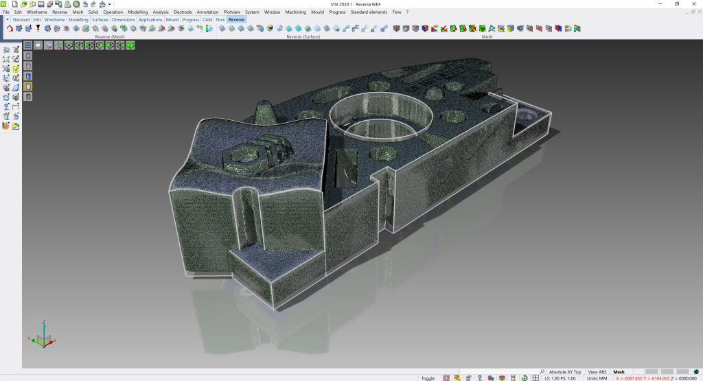
The Reverse module has been enhanced with additional functionalities for both Reverse and Casting processes, including new features to support the scanning to surfaces generation.
Cafasso says features such as radius generation from mesh, plane generation, adapt mesh on boundary, and sectional curves on mesh, provide greater benefit for the reverse process from point scanning to solid model generation. "A new Best Fit feature aligns a stock model to the final solid model by setting tolerances on different faces. This is extremely useful for the casting market, as it allows the cast model to be scanned, achieving a best fit alignment with the final geometry, producing an optimized toolpath with reduced machining time." The stock model can then also be used for machining simulation purposes.
The Compare feature has been improved to provide an enhanced graphical evaluation of the results, and to display distances between the scanned model and the final solid model. "The enhancements achieved provide quality improvements to both processes, as well as time saving from the scanning to the manufacturing process," Cafasso says.
A new body-to-mold functionality has been introduced, which provides a quick solution to define the correct position and orientation of a plastic part on the tool. The feature allows the transformation of the model from the "car in line" position to the mold position, and to apply the required shrinkage value. "The original position of the model can also be restored if modifications are required for the molding of the part. This is extremely useful especially, but not only, for the automotive market, as it provides a time saving for the mold design process," Cafasso says.
Cafasso says that a new automatic deburring function reduces the set-up time for that vital aspect of the overall process. "Creating CAM operations on any arbitrary part geometry is relatively easy nowadays, as parts can be virtually designed, created and produced. However, once CAM is finished there is one last operation that is not yet automated, and is usually done manually after machining. Burrs occur on all parts that have straight edges or non-tangent outer surface topologies. They appear when the tool is chipping the metal off that edge. It's an unwanted situation because it can destroy the functionality of the part and can even be a danger to the worker, as it's razor sharp. So, most of the time it's essential to remove it."
The purpose of VISI's deburring strategy is to provide automatic finishing to the machined part's sharp edges – an important phase of the manufacturing process for parts with no tangent surfaces. It creates a highly automated toolpath to deburr sharp edges of a workpiece with a spherical tool. The tool is positioned in the bi vector of the automatically detected sharp edges. Automatic tilting and linking is then applied to avoid collisions. "As the whole process is highly automated, this machining strategy significantly reduces deburring setup time," Cafasso says.
Additionally, the 5-axis Autotilting capability has been enhanced in VISI 2020.1, with new smoothing options, based on a more sophisticated interpolation algorithm. This optimizes the contour while keeping the tilt angles in a limited range, resulting in a more fluent movement of the machine while milling the part.
New graphical representations assist in validating the model for manufacturing purposes. The Undercut and Accessibility shading also identifies undercut areas during the design and modelling phases. "The advantage provided is the ability to validate a model for manufacturing purposes at an early stage in the design to manufacturing process," Cafasso says.


