WorkNC 2018 R1 Software
WorkNC 2018 R1 Software
The newly-released version of WorkNC from Vero Software introduces two important new tools to the portfolio: a direct modelling CAD system and a Robot Module, making offline programming of robots easy, even for inexperienced users. Described as "the right CAD for CAM," WorkNC Designer is a powerful new application focusing on the specific needs of machinist programmers, enabling users to create designs or modify existing geometry from third-party CAD systems.

The newly-released version of WorkNC from Vero Software introduces two important new tools to the portfolio: a direct modelling CAD system and a Robot Module, making offline programming of robots easy, even for inexperienced users. Described as "the right CAD for CAM," WorkNC Designer is a powerful new application focusing on the specific needs of machinist programmers, enabling users to create designs or modify existing geometry from third-party CAD systems.
WorkNC Designer is built on the Parasolid technology, bringing hybrid modelling and direct modelling capabilities that will revolutionize the way programmers prepare parts for manufacturing. WorkNC Brand Manager Miguel Johann says, "It's not dependent on having a series of parameters that drive it, or a feature tree. It provides a very quick, dynamic editing and modelling environment, where users simply sketch, drag, hold, push or twist, to create and modify models."
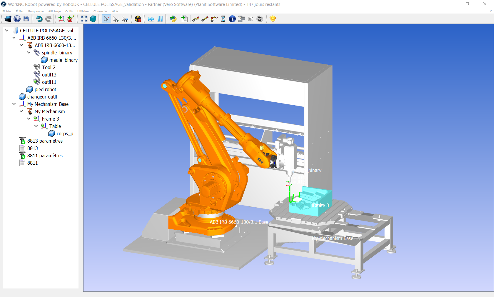
The second major item of new functionality is the Robot Module. "As robots are becoming more commonplace on the shop floor, there is an increasing need to provide offline programming for them. New simulation and singularity resolution tools in WorkNC 2018 R1 mean users can take full advantage of the enormous benefits robots bring to the manufacturing process," Johann says. "For example, they free toolpaths from the limitations of milling, as the tool at the end of the robot's arm can also be a grinder, a laser head, a welding nozzle, or indeed, any other tool that engineering creativity can think of.
"Robots also allow for the tool to be fixed, and the part to be moved around it, instead of the traditional method of a fixed component and moving tool. But robots are only as good as the software programming them, and this latest development in WorkNC 2018 R1 ensures that manufacturers can be at the cutting edge of robot technology."
A number of new features have been incorporated into Waveform Roughing which improve efficiency and performance. These include support for new tools in trochoidal machining strategies, allowing for ramped lead-ins with high angles, typically between ten and 20 degrees.
Algorithms concerning the Z-step Auto Variable Strategy have been revised and improved, allowing for a smoother toolpath distribution on the part. "Also, with improvements to Tapping and Threading, it's now possible to define Surface Selection in the Machining Zone section of the toolpath menu. Previously, surface management was fully automatic, and it wasn't possible to ignore surfaces or add optional surfaces," Johann says.
A major highlight is a change to the way part activation is managed, allowing for a rougher, lighter and simpler model to be used by Roughing Toolpaths, speeding up calculation times. In earlier versions of the software, one set of activation parameters was applicable for all types of toolpaths in a given work zone. Now, two sets can be defined by users, and Johann says setting specific values for roughing toolpaths creates a different mesh model, cutting calculation times by up to half.
The new Stock Initialization feature generates a stock model for just a specific area of a component, defined by selected surfaces. This is particularly useful when only certain areas of a part need to be repaired.


