CAM program keeps pace with part complexity
CAM program keeps pace with part complexity
Overcome a CAM system's limitations when transitioning to machining more complex parts. New CAM software.
END USER: Castle Precision Engineering Ltd., +44 141-6341377, www.castleprecision.com.
CHALLENGE: Overcome a CAM system's limitations when transitioning to machining more complex parts.
SOLUTION: New CAM software.
SOLUTION PROVIDER: DP Technology Corp., (805) 388-6000, www.dptechnology.com.
After Jack Tiefenbrun founded Glasgow, Scotland-based Castle Precision Engineering Ltd. in 1951, Singer Sewing Machine Co. became the company's largest customer. Fast forward to the present and Castle focuses mainly on producing aerospace engine parts.
While transitioning to ever higher value-added, increasingly complex parts to better differentiate itself in the global market, Castle found that its CAM software lacked sophistication and was limited when trying to keep up with the demands of the new parts, noted Operations Director Yan Tiefenbrun. The limitations included effectively handling complex back boring and controlling RTCP (rotation tool center point) movement, he said. "Essentially, when we were transitioning to new 5-axis machining strategies, our CAM software really struggled."
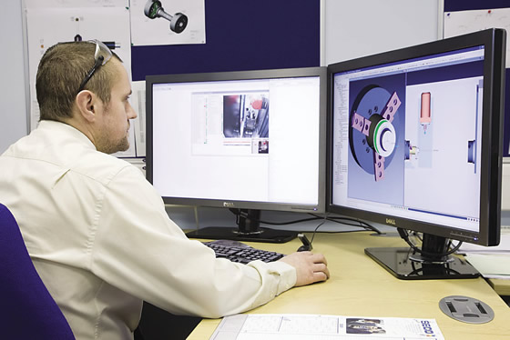
A manufacturing engineer at Castle Precision Engineering uses ESPRIT CAM software, which is integrated with the part manufacturer's front-end SolidWorks CAD software and back-end Vericut simulation software (shown on the right-hand screen).
In addition, the CAM supplier didn't serve customers in a timely manner, Tiefenbrun said. "We were going through a reseller in the U.K., who was communicating with the U.S., who was communicating with Germany, who was communicating with other countries. By the time we got someone, it had gone through so many different people that we were 3 to 6 months in line. This was just far too slow for us."
Also problematic was the process of receiving software changes, which required the CAM developer to generate complex pieces of code that weren't necessarily proven out. "We would usually not just be waiting for it," Tiefenbrun said, "but we would be the guinea pigs as well."
As a result, Castle began the "intense" and "methodical" process of obtaining a new CAM package by requesting full demonstration versions from several developers, he explained. To test the packages against the same baseline, Castle designed a fantasy part that had all the features the manufacturer recognized as having caused past CAM failures. "We referred to it as the CAM killer," Tiefenbrun said.
All the CAM systems excelled in some areas but not others, and Castle determined that none of the ones tested proved an adequate fit. However, Castle has a strong relationship with DMG Mori Seiki Co. Ltd. and the machine builder recommended ESPRIT CAM software from partner-company DP Technology Corp., Camarillo, Calif. Tiefenbrun added that about half of the 70-plus CNC machine tools at Castle's 100,000-sq.-ft. facility are from DMG Mori.
Although previously unaware of that CAM package, being a strategic partner with the machine builder prompted Castle to investigate ESPRIT and then purchase it, Tiefenbrun said. "It was the relationship between those two companies that was critical."
That relationship includes the two companies working together to create post-processors for the CAM software based on the kinematics of DMG Mori's machines, Tiefenbrun added. "The post-processors are gold-stamped and verified by Mori Seiki," he said. "We don't worry about any machine updates affecting the post-processors. That's all done through Mori Seiki and ESPRIT."

Castle Precision Engineering machines a fan disc for a customer.
In addition to its easy integration with those machines, Castle chose ESPRIT because of its interoperability with SolidWorks CAD software and Vericut toolpath verification and simulation software, according to Tiefenbrun. Although he acknowledges the CAM software's link with the front-end CAD package is good but not as effective as some, the link with the back-end verification software is seamless and "hugely important" to the company.
Tiefenbrun explained that the high level of transparency for the back-end link enables Castle to adhere to its strict "zero edit" policy. The policy mandates that once a CAM program is verified as being able to exactly replicate the machining processes on the shop floor, it cannot be altered without going through the controlled, centralized environment, where it is reprocessed via simulation to ensure no errors are in the code. "We absolutely must guarantee that it's right the first time," he said.
Not only can a scrapped part turn a development forging into a $100,000 boat anchor or lawn ornament, Tiefenbrun pointed out that it can have a severe negative impact on a customer's development program because the lead time for such a forging can be up to 18 months.
He noted ESPRIT has helped Castle Precision Engineering reduce its number of machining operations, which eliminates a significant amount of transfer and setup time—as well as potential human error. More importantly, however, ESPRIT provides Castle with the capability to produce products that the parts manufacturer couldn't previously because of the previous CAM software's limitations. "We get the quality that we're looking for," Tiefenbrun said, "and are on time on very complex projects."