Counteracting gravity
Counteracting gravity
The vertical linear axes on machine tools are fundamentally different than those that operate parallel to the ground. This is because the actuators on the vertical axes have to overcome the effects of gravity.
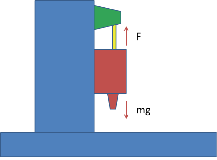
The vertical linear axes on machine tools are fundamentally different than those that operate parallel to the ground. This is because the actuators on the vertical axes have to overcome the effects of gravity. In addition to the forces required to accelerate the axes, the weight of the moving elements imposes a constant load that servomotors or other actuators must carry to hold the axes in position (Figure 1).

Courtesy of All images courtesy S. Smith
Figure 1. The servomotor carries the weight of vertical axis components. The vertical moving elements are red, the servomotor is green, and the ballscrew is yellow. The force supplied by servomotor F carries the weight of the moving elements, which equals m×g, where m is the mass, and g is the gravitational acceleration.
On small machine tools, that load may be small enough to ignore, but on larger tools, the power required to hold against the weight is significant. Power costs money, and power is eventually transformed into heat that is conducted into the machine tool structure.
In many machines, the weight of the vertical moving components is enough to drive the ballscrew backward if the servomotor loses power. Therefore, each vertical axis has a brake, which requires power to release. If power to the vertical actuator is turned off or lost, the brake is engaged before the axis can drop.
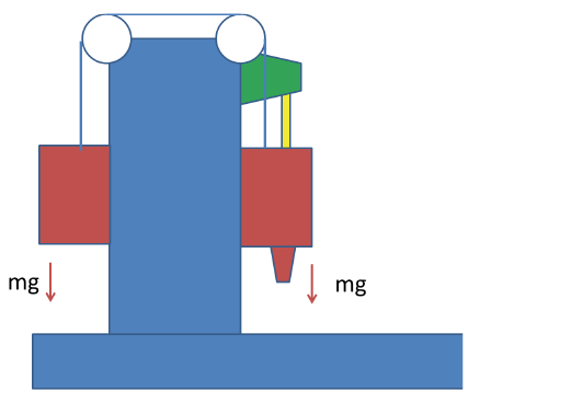
Several methods are commonly employed to reduce the weight load on the vertical actuator. An obvious solution is a counterweight (Figure 2). In the figure, a mass equal to the mass of the original vertical components has been added. The two masses are connected by a cable-pulley system to balance them, and the servomotor only has to supply the force needed for acceleration.

Figure 2. A counterweight balances the weight of the vertical axis components.
However, at least two problems exist with this solution. The first is that, while the counterweight balances the force, it doubles the moving mass. Because the servomotor supplies the force to accelerate the mass, it must accelerate both the mass and the counterweight. This reduces achievable axis acceleration. The second problem is the connecting cable is relatively flexible. When motion starts or stops, the cable may become a source of vibration.
Another solution to the gravity problem is use of a mechanical spring to produce a constant force that opposes the weight over a long displacement range. Unfortunately, constant-force springs are essentially only available for short strokes. A stack of Bellville washers that provides the spring force for machine tool clamping is a notable example, but outside of its short stroke range, the force is not constant.
A third solution involves an active hydraulic or pneumatic actuator. In this case, the counterbalance force comes from a piston-cylinder arrangement, using air or oil as the working fluid. As the axis moves, the volume inside the cylinder changes and the pressure in the cylinder must be actively controlled to keep the counterbalance force constant. The load carrying capacity of a hydraulic cylinder is typically higher than that of a pneumatic cylinder, but hydraulic cylinders also typically have lower operating bandwidths, because the mass of hydraulic fluid must also be moved.
Most machine tools have at least one axis that moves in a direction where gravity is a factor. Multiple approaches are available to manage the weight, each with advantages and disadvantages. Machine tool designers are always challenged to weigh the pros and cons and select the best compromise of cost, performance and efficiency. CTE
About the Author: Dr. Scott Smith is a professor and chair of the Department of Mechanical Engineering at the William States Lee College of Engineering, University of North Carolina at Charlotte, specializing in machine tool structural dynamics. Contact him via e-mail at [email protected].


