A unique manual milling method is available for generating geometrically true spherical surfaces. This technique can be used to machine convex and concave spherical surfaces. Other than the milling machine, the only tools needed are a boring head and a rotary table.
If you have a CNC lathe or mill, this is really just an academic exercise. The technique is interesting in that it is self-correcting and self-proving, which is not true of CNC equipment. If you don’t have any CNC machines, you can add a neat trick to your toolbox.
I learned this technique years ago from my old toolmaker friend Charlie. When he first told me about it, I was skeptical until I tried it. If you have a computer drafting program, you can make short work of the math and setup angle. This method is far superior for forming tools and beats the pants off swinging arc fixtures because the spherical surface is a true geometric generation. The spherical form is limited only by the accuracy of the machine spindle and the rotary table—two intersecting circular paths that produce a true spherical surface.
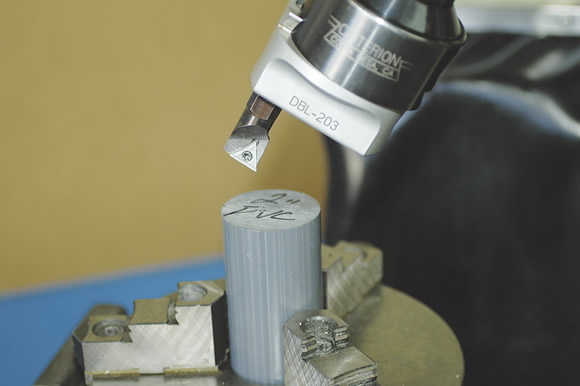
Courtesy of All images: T. Lipton
When working with a convex surface, the cutting edge faces inward.
Imagine a cutting tool that only cuts a hollow circle, kind of like a hole saw. When the tool is set at an angle other than the axis of the rotary table and the part is rotated under the tool, a spherical surface is generated.
The boring head is tipped at an angle that represents the chord of the desired spherical segment. A single-point cutting tool is applied and, depending on whether the form is concave or convex, the cutting edge is reversed. For convex surfaces, the cutting edge faces inward. For concave surfaces, the cutting edge faces outward, as it would in normal boring head work.
As the tool is advanced into the workpiece, the rotary table is rotated through 360°. The rotary table is also fed into the tool along the X-axis.
When you first try this method, use plastic so you can quickly see exactly what is happening before you try it on important parts. There are three variables you must understand to get controllable results. The first involves basic calculations. The second is the setup and the third is the execution—actually doing it.
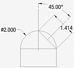
A graphical setup for cutting a full hemisphere 2 " in diameter.
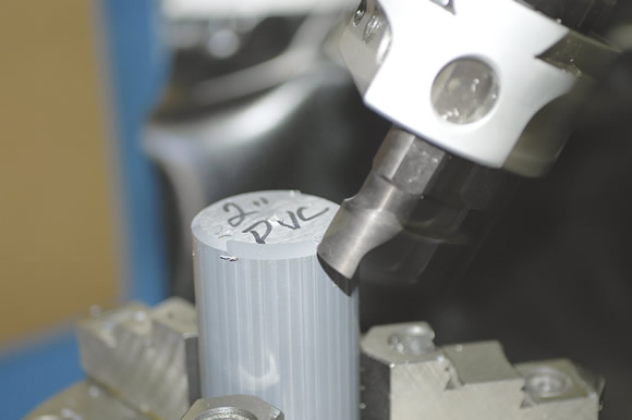
When working with a concave surface, the cutting edge faces outward as it would in normal boring head work.
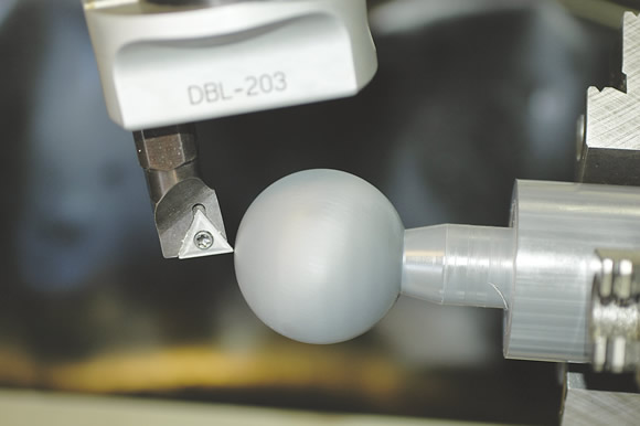
The spherical surface generation technique can produce a full sphere.
A single-point cutting tool sweeps through a circle that has no thickness on one side of the cutting edge. If you think about how a ring of any size smaller than the spherical surface can lay in full contact with the sphere, you can visualize how the cutting action takes place.
The material that projects into the ring is cut as the part rotates under the cutting tool. This leaves a spherical surface the size of the ring. Any plane that cuts through a sphere produces a true circle, no matter what the angle.
In the hemisphere illustration, we can see the basic graphical setup for cutting a full hemisphere 2 " in diameter. The chord in this case is 1.414 ". This is the diameter the boring head would be set at (1.414 ") or a little larger to cut the 2 " diameter. The spindle would be tilted 45° relative to the rotary table axis to cut a full hemisphere. You can see from the drawing that no other angle would produce a full hemisphere. This axis of the spindle must be perpendicular to the segment chord. The spindle centerline is the midpoint of the chord. The chord is also the hypotenuse of the right triangle, which is the maximum rise of the radius and the distance from the centerline to the endpoint of the arc.
For other radii and partial segments, a little math is required to get the chord and the angle. We can use our drawing example to illustrate the math. There is no official name for the diameter the boring head is set to, so I call it the “swept diameter” (SD). For OD work, the SD should be set at the chord size or larger. For ID work, the SD should be set smaller or the same as the chord.
Angles less than 45° produce less than a full hemisphere. Angles greater than 45° produce greater and greater portions of the sphere until you reach a maximum of 180° for a full sphere. Once you go past 45°, the boring head must be set accurately to the chord length before you reach the finish diameter. You can adjust this as you rough the part, taking measurements as you go.
In actual practice, you can’t cut a full sphere in one setup. You still have to hold the part and rotate it somehow. To produce a full sphere, you must use two separate holding setups. CTE
About the Author: Tom Lipton is a career metalworker who has worked at various job shops that produce parts for the consumer product development, laboratory equipment, medical services and custom machinery design industries. He has received six U.S. patents and lives in Alamo, Calif. Lipton’s column is adapted from information in his book “Metalworking Sink or Swim: Tips and Tricks for Machinists, Welders, and Fabricators,” published by Industrial Press Inc., New York. The publisher can be reached by calling (888) 528-7852 or visiting www.industrialpress.com. By indicating the code CTE-2013 when ordering, CTE readers will receive a 20 percent discount off the book’s list price of $44.95.
Related Glossary Terms
- boring
boring
Enlarging a hole that already has been drilled or cored. Generally, it is an operation of truing the previously drilled hole with a single-point, lathe-type tool. Boring is essentially internal turning, in that usually a single-point cutting tool forms the internal shape. Some tools are available with two cutting edges to balance cutting forces.
- boring head
boring head
Single- or multiple-point precision tool used to bring an existing hole within dimensional tolerance. The head attaches to a standard toolholder and a mechanism permits fine adjustments to be made to the head within a diameter range.
- computer numerical control ( CNC)
computer numerical control ( CNC)
Microprocessor-based controller dedicated to a machine tool that permits the creation or modification of parts. Programmed numerical control activates the machine’s servos and spindle drives and controls the various machining operations. See DNC, direct numerical control; NC, numerical control.
- gang cutting ( milling)
gang cutting ( milling)
Machining with several cutters mounted on a single arbor, generally for simultaneous cutting.
- inner diameter ( ID)
inner diameter ( ID)
Dimension that defines the inside diameter of a cavity or hole. See OD, outer diameter.
- lathe
lathe
Turning machine capable of sawing, milling, grinding, gear-cutting, drilling, reaming, boring, threading, facing, chamfering, grooving, knurling, spinning, parting, necking, taper-cutting, and cam- and eccentric-cutting, as well as step- and straight-turning. Comes in a variety of forms, ranging from manual to semiautomatic to fully automatic, with major types being engine lathes, turning and contouring lathes, turret lathes and numerical-control lathes. The engine lathe consists of a headstock and spindle, tailstock, bed, carriage (complete with apron) and cross slides. Features include gear- (speed) and feed-selector levers, toolpost, compound rest, lead screw and reversing lead screw, threading dial and rapid-traverse lever. Special lathe types include through-the-spindle, camshaft and crankshaft, brake drum and rotor, spinning and gun-barrel machines. Toolroom and bench lathes are used for precision work; the former for tool-and-die work and similar tasks, the latter for small workpieces (instruments, watches), normally without a power feed. Models are typically designated according to their “swing,” or the largest-diameter workpiece that can be rotated; bed length, or the distance between centers; and horsepower generated. See turning machine.
- milling
milling
Machining operation in which metal or other material is removed by applying power to a rotating cutter. In vertical milling, the cutting tool is mounted vertically on the spindle. In horizontal milling, the cutting tool is mounted horizontally, either directly on the spindle or on an arbor. Horizontal milling is further broken down into conventional milling, where the cutter rotates opposite the direction of feed, or “up” into the workpiece; and climb milling, where the cutter rotates in the direction of feed, or “down” into the workpiece. Milling operations include plane or surface milling, endmilling, facemilling, angle milling, form milling and profiling.
- milling machine ( mill)
milling machine ( mill)
Runs endmills and arbor-mounted milling cutters. Features include a head with a spindle that drives the cutters; a column, knee and table that provide motion in the three Cartesian axes; and a base that supports the components and houses the cutting-fluid pump and reservoir. The work is mounted on the table and fed into the rotating cutter or endmill to accomplish the milling steps; vertical milling machines also feed endmills into the work by means of a spindle-mounted quill. Models range from small manual machines to big bed-type and duplex mills. All take one of three basic forms: vertical, horizontal or convertible horizontal/vertical. Vertical machines may be knee-type (the table is mounted on a knee that can be elevated) or bed-type (the table is securely supported and only moves horizontally). In general, horizontal machines are bigger and more powerful, while vertical machines are lighter but more versatile and easier to set up and operate.
- milling machine ( mill)2
milling machine ( mill)
Runs endmills and arbor-mounted milling cutters. Features include a head with a spindle that drives the cutters; a column, knee and table that provide motion in the three Cartesian axes; and a base that supports the components and houses the cutting-fluid pump and reservoir. The work is mounted on the table and fed into the rotating cutter or endmill to accomplish the milling steps; vertical milling machines also feed endmills into the work by means of a spindle-mounted quill. Models range from small manual machines to big bed-type and duplex mills. All take one of three basic forms: vertical, horizontal or convertible horizontal/vertical. Vertical machines may be knee-type (the table is mounted on a knee that can be elevated) or bed-type (the table is securely supported and only moves horizontally). In general, horizontal machines are bigger and more powerful, while vertical machines are lighter but more versatile and easier to set up and operate.
- outer diameter ( OD)
outer diameter ( OD)
Dimension that defines the exterior diameter of a cylindrical or round part. See ID, inner diameter.
- sawing machine ( saw)
sawing machine ( saw)
Machine designed to use a serrated-tooth blade to cut metal or other material. Comes in a wide variety of styles but takes one of four basic forms: hacksaw (a simple, rugged machine that uses a reciprocating motion to part metal or other material); cold or circular saw (powers a circular blade that cuts structural materials); bandsaw (runs an endless band; the two basic types are cutoff and contour band machines, which cut intricate contours and shapes); and abrasive cutoff saw (similar in appearance to the cold saw, but uses an abrasive disc that rotates at high speeds rather than a blade with serrated teeth).