Give threading a whirl
Give threading a whirl
Thread whirling is a productive way to quickly make certain thread forms.
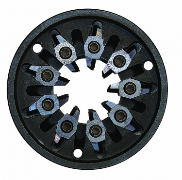
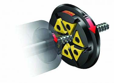
Although similar to thread milling, thread whirling has inserts mounted on the inside of a cutting ring, or cutter holder, rather than on the outside of a milling tool. The thread whirling ring rotates around a cylindrical component to cut a thread in one pass.
A productive method often used for thread forms that need to be produced quickly and at tight tolerances, typical parts for thread whirling are medical bone screws, implants, feed screws, worm gears and other microcomponents.
Swiss-style CNC machines use thread whirling to generate complex, complete thread forms that normally would be difficult to produce efficiently in high volumes. Thread whirling is a milling process used primarily for thread forms that require large amounts of removed material, such as medical buttress threads designed to thread into bone.
Thread whirling is important to manufacturers of implant screws, for which orders can range from 1,500 to 5,000 pieces or more per production run. Bone screws are being designed with more complex thread forms, including deep threads, multiple leads and unique thread pitches. Inserts are designed and manufactured specifically for individual threads.

Shown above is a typical arrangement of cutting inserts in a thread whirling ring, which affixes to the dedicated live tooling attachment used to perform the process. Image courtesy of Genevieve Swiss Industries
"Thread whirling can be used to produce worm gears and of course standard 60-degree UN threads, as well as metric standard threads," said Scott Laprade, applications supervisor at Westfield, Massachusetts-based Genevieve Swiss Industries Inc., which does business as GenSwiss.
The company specializes in tooling and accessories for Swiss-style machining and has expertise with thread whirling given its exclusivity to Swiss machines.
GenSwiss has partnered with Utilis AG of Müllheim, Switzerland, since 2006, and the companies have worked to further the technology used in this machining process. Laprade said Utilis and GenSwiss introduced to the Swiss-turn industry thread whirling systems that use up to 12 thread cutting inserts. The addition of tooling with more cutters enabled users of whirling attachments to increase productivity over the conventional three- and six-insert systems that were available at the time.
Another company, Sandvik Coromant Co. in Fair Lawn, New Jersey, provides CoroMill 325 thread whirling rings and inserts, which meet the needs of a large number of sliding-head machine types. The rings and inserts can thread long, slender components from rough stock at high speeds without use of a dedicated thread whirling machine, said Patrick Loughney, who handles business development for small part machining and is product specialist for indexable drilling tools.
He said most thread whirling is performed on a sliding head on a Swiss-style machine.
"These machines offer the most stable cutting condition due to the bar stock being supported by a guide bushing that is in the machine's spindle/chuck, where the material is fed through the guide bushing, allowing for the cutting tools to be very close to the material being machined," Loughney said. "The machine must have a c-axis that the thread whirling unit is driven by. The thread whirling ring fits into the unit. The rings consist of multiple indexable carbide inserts with up to three cutting edges depending on the pitch of the thread."
Advantages
Thread whirling offers several advantages over single-point threading. First, users can machine high-quality threads on long, slender components without the risk of bending or vibrating. Single-pass threading from stock diameter reduces cycle time, increases productivity and helps produce accurate threads by tilting the whirling ring toward the helix angle. Also, good chip control enables continuous machining, and finishing treatment is not required. Finally, deep thread forms, such as Acme, can be achieved easily with thread whirling.

Although similar to thread milling, thread whirling has inserts mounted on the inside of a cutting ring, or cutter holder, rather than on the outside of a milling tool. The thread whirling ring rotates around a cylindrical component to cut a thread in one pass. Image courtesy of Sandvik Coromant
"Speed is the main advantage," Laprade said.
He said whirling can produce long threaded parts accurately and efficiently with exceptional surface finishes, whereas traditional single-point threading methods require multiple passes with a threading tool. An additional advantage is that aggressive, deep thread forms can be achieved in a single pass with a high level of precision.
Long threads pose a further hurdle when machined on a Swiss-style CNC machine. Because Swiss machines use a guide bushing to support material, which moves through the tooling rather than the tooling moving to the workpiece, Laprade said long threaded parts must be pulled back through the guide bushing after being cut, resulting in lost support of the workpiece.
"Once material support is removed," he said, "a machinist runs the risk of the part deflecting under the tool pressure with each subsequent pass. Thread whirling eliminates this concern, and it can take stock diameter and machine it to a complete thread in a single shot."
Loughney said when using a sliding-head machine, users have the support of its guide bushing close to the cutting head, with multiple inserts applying even cutting pressure. Trying to thread long, slender components using a single-point method would be almost impossible and could cause high scrap rates, poor-quality threads and excessive tool wear and breakage.
The improvement in surface finish from thread whirling is a result of the unique tangential cutter path and increased rigidity. Burrs also are minimized due to reduced chip loads and longer tool life.
Compared with thread milling a zero-degree thread wall, which commonly is found on the trailing side of a bone screw thread, the finish pattern of thread whirling is better thanks to the tangential radial entry and exit of the cutter, which leaves a uniform pattern.
With thread milling, the tool cuts on the way into the material and up to the full tangent point. As the heel of the cutter makes an exit path, the direction of the finish pattern changes and results in a crosshatch pattern.
With thread whirling, the cutter enters and exits in a radial arc, which is similar to the thread radius direction. As the heel of the insert exits the thread form, the resulting finish leaves a crosshatch pattern. But this pattern would not be seen on any thread wall with a positive wall angle. That is because the cutter contacts the workpiece only at the full tangency of the cutting path.
Best Practices
Loughney said getting thread whirling right from the beginning, setting up and understanding how the thread whirling unit works on a machine are critical for first-time users.
"Many thread whirling units have a 50-1 gearbox reduction," he said. "Take this into consideration that the programmed rpm will not be the actual output in most cases."

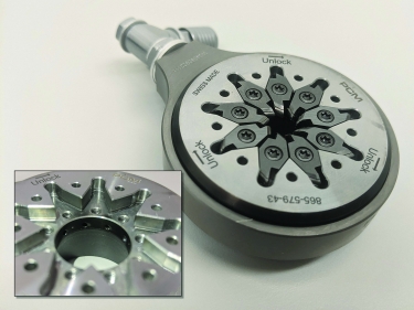
Internally cooled thread whirling rings eliminate the need to have perfectly aimed coolant nozzles for chip evacuation and insert cooling. Cutting oil is delivered to the insert edge through internal channels in the cutter ring. Image courtesy of Genevieve Swiss Industries
Standard inserts for thread whirling HA and HB thread forms are available as stocked items from Sandvik Coromant. These threads have the specific dimensions and tolerances needed for bone screws and other medical implants. However, the majority of thread forms on bone screws are special forms that would be offered as engineered solutions.
As with everything else for a Swiss-style CNC machine, Laprade said thread whirling depends on the guide bushing for support, so ensuring that cutters are as close as possible is paramount, especially for smaller-diameter threads.
"To help accommodate that," he said, "shifted cutter rings that bring the inserts closer to the guide bushing are available for more readily available live tooling attachments on the market."
Recent Advancements
One of the most recent improvements for thread whirling has been cutter rings that are capable of delivering high-pressure cutting oil directly to threading inserts to better clear chips, as well as cool the cutting edges.
"Previously," Laprade said, "this had been accomplished through external cooling lines that had to be manually adjusted for each setup and (were) time-consuming."
Another recent advance is quick-change capability. Sandvik Coromant provides that with its whirling rings, along with high-quality carbide and coatings, such as Grade GC1105, which Loughney said is a popular choice for medical machining.
"Grade GC1105 offers sharper edges for burr-free component surfaces and long and predictable tool life," he said. "This is especially important when machining titanium and stainless steel bone screws."
Advantages of Thread Whirling
According to GenSwiss, thread whirling offers advantages over single-point threading, including:
- Deep threads. Bone screws usually have a deep thread formation, like Acme forms and other increased-pitch threads, which can be machined in less time by whirling.
- Long-length-to-diameter threads. On a Swiss-type machine, a thread whirling spindle works close to the guide bushing for increased support and rigidity on long-length-to-diameter screws.
- Faster setup. By eliminating the need to match rough and finish insert forms, thread whirling reduces setup and debugging time.
- Increased productivity. Thread whirling usually is performed in a single pass from stock diameter. By eliminating unnecessary support devices and multiple thread passes, a cycle can be reduced by minutes.
- Greater tool life. Whirling inserts have a stronger cutting edge than single-point tools.


