Shop Operations: Chamfering and edge dressing
Shop Operations: Chamfering and edge dressing
The expression "There's more than one way to skin a cat" certainly applies to machining. A young programmer in our shop is constantly being run in circles by the whims of those in authority. Newcomers are in a difficult position; they not only lack experience, they generally want to please everybody.
The expression "There's more than one way to skin a cat" certainly applies to machining. A young programmer in our shop is constantly being run in circles by the whims of those in authority. Newcomers are in a difficult position; they not only lack experience, they generally want to please everybody.
For example, there are numerous ways to apply edge dressings to a part, and some work better than others. Presented here are methods that may make it easier to apply these common features.


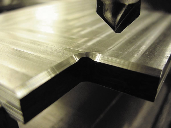
Shown is an inconsistent chamfer on an inside radius. This was because the Z height of the chamfering-tool/" data-glossary-id="142011" data-glossary-teaser="Cutter or wheel that creates a beveled edge on a tool or workpiece." title="Cutter or wheel that creates a beveled edge on a tool or workpiece." aria-label="Glossary: chamfering tool">chamfering tool wasn't set correctly. All images courtesy J. Harvey.

Chamfering is not as easy as it looks on a computer. The point of a sharp chamfering tool does not cut well and will generate a burr if programmed to cut on center around the profile of a part. This is because not much chip clearance is available at the end of a pointed chamfering tool and the cutting speed at the tip of a pointed tool is, theoretically, zero. Also, the tool tip may not be precisely sharp.
For a chamfering tool to cut cleanly, the tool tip must be offset from the profile. In a new version of the CAM software I use, a chamfering tool can now be offset to cut a clean profile.
If you offset a chamfering tool to cut cleanly, the depth of the tool must be correct. If the depth is not correct, the tool can produce inconsistent chamfers on the inside radii. This can be overcome with thoughtful planning. However, when it boils down to trivial features, I don't like to think too much. I prefer to let the computer do the thinking.
For most chamfering, use a ballnose or hognose endmill and program the chamfer with a 3D cut. Using this method, the computer does all the thinking for you and you don't have to worry about burrs, offsetting the tool or inconsistent chamfers. The only thing you have to concern yourself with is choosing a cutter with a radius smaller than the smallest inside radius of the part. The downside is that chamfers may take a bit longer to cut because you are taking multiple passes to create the chamfer. I usually go full throttle when chamfering this way.


A ballnose endmill cuts an edge radius around a hole using the 3D method.

The programmer I previously mentioned got into hot water using this method. A component needed a 0.1" chamfer around the perimeter and the center window. The customer was waiting for the part and would frequently go to the machine to check on its progress.
The chamfer operation was painfully slow, and the customer was getting agitated. Afterward, I told the well-intentioned programmer that he'd better push hard on the accelerator if he was going to chamfer using the 3D method. The parameters he was using were 7,000 rpm, a 100-ipm feed rate and a 0.002" step-over, which collectively resulted in the operation taking 29 minutes. The biggest mistake is the small step-over moves, which are set in the G code and can't be adjusted at the machine. In hindsight, it's easy for me to second-guess his settings, but I would have chosen 10,000 rpm, a 300-ipm feed and a 0.006" step-over, resulting in the operation taking 3.8 minutes.
Cut edge radii using the 3D method. You can use a radius tool to radius edges, but radius tools are a little tricky to setup and adjust. I prefer using a ballnose endmill to cut soft material, such as aluminum, and a hognose endmill to cut steel. That way the computer does all the thinking and little, if any, adjustment is needed. A hognose endmill cuts with less pressure than a ballnose, because less cutting edge contacts the material.
With fillets and chamfers being easy to apply with CAD software, designers routinely add them to their solid part models because they look "pretty." Many don't realize that chamfers and radii are much more time-consuming to cut than to model.


