Still more CNC lathe tips

Author Tom Lipton
Published
March 01, 2014 - 10:45am

Following the theme of the past two columns, here are some additional tips and tricks for operating a CNC lathe.

A handy trick for cutting diameters and parts outside the maximum turning diameter of a lathe involves a custom shop-made tool (Figures 1a and 1b). With this tool, I increased turning capacity from 9 " to more than 15 ". To create the tool, I cut the end off of a CCGX insert toolholder and welded it to a cold-rolled steel shank. Be sure to tack weld it first, then check the machine movement for the required clearances and travels before solidly welding it. This setup puts the tip much further back than what is possible with standard OD tools.

Ch08.Fig026.Lipton.DSC_6287.tif
All images courtesy of T. Lipton

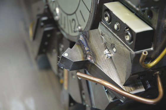
Figure 1a. This custom turning tool increases capacity on a CNC lathe.

Ch08.Fig027.Lipton.DSC_6290.tif

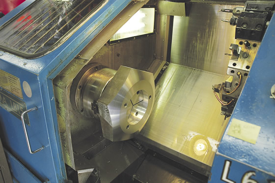
Figure 1b. I used the custom turning tool to make this aluminum hexagon.

Figure 2 shows a method to proof programs and even verify part dimensions. I make several test blanks from medium-density fiber board laminated together with glue to get any blank size I need. I adhere the bandsawed laminations together with white carpenter’s glue and then clamp them. MDF board is quite accurate in thickness and, more importantly, in flatness, and is cheaper and easier to use than huge blocks of wax or expensive butter board. It has no grain, so it is easier to cut than solid wood or plywood.

Ch08.Fig028.Lipton.DSC_6310.tif

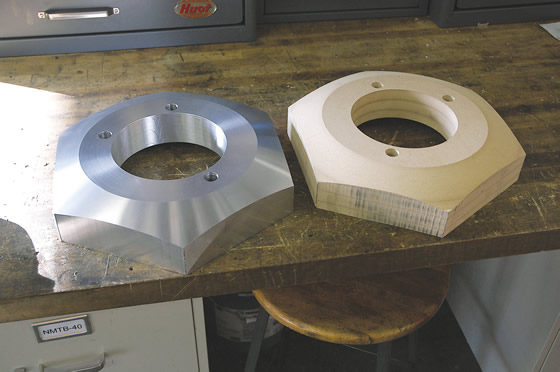
Figure 2. I make several test blanks from medium-density fiber board laminated together to proof programs and even verify part dimensions.

Figure 3 shows another lathe quick-change tool. Commercially available, quick-change tooling systems are quite expensive and don’t lend themselves to highly varied job shop work. I had several special bushings made that match the taper of cheap and readily available endmill holders. These bushings have the required precision-ground tapers and locating keys, so the tool indexes accurately. The pictured holder is an NMTB holder, but almost any taper would work. I like the NMTB because it has a standard coarse thread for the retention knob. I just put a bolt in the back and I can switch between tools in seconds rather than minutes or hours.

Ch08.Fig030.Lipton.DSC_5461.tif

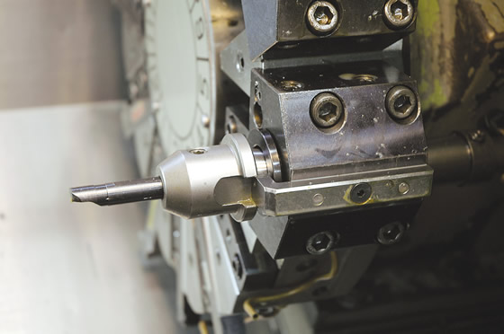
Figure 3. An ID grooving tool is held in a quick-change system using a standard NMTB endmill toolholder. This quick-change setup is generally for ID tools, which typically take a long time to set up in a CNC lathe.

Changing the power chuck on a large CNC lathe can be a real hassle. I made a special for helping reduce changeover time from chuck to collet closer to 30 minutes instead of an hour or more (Figure 4). This pivoting tool clamps in an unused tool position in the turret, and the turret is jogged around to help remove or reposition the chuck. Once the chuck is off the hydraulic drawtube, the chuck can be swung out the door. In Figure 5 (page 38), the chuck is going on the machine. I use two guide pins that fit the retaining bolt hole minor diameter to guide the chuck into position and align with the drawtube.

Ch08.Fig031.Lipton.MVC-327F.tif

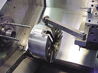
Figure 4. This special helps reduce changeover time from chuck to collet closer to 30 minutes instead of an hour or more.

Ch08.Fig033.Lipton.MVC-329F.tif

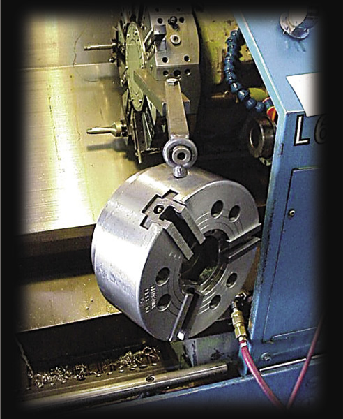
Figure 5. Once the chuck is off the hydraulic drawtube, the chuck can be swung out the door.

Spray some WD-40 on the inside of the window of a CNC lathe to help keep the window somewhat clear when testing a program. Anyone who has desperately tried to see clearly through the coolant shower while testing a new program will appreciate this tip.

Many of the tips I presented about CNC lathes are related to setup reduction, because a long setup is a roadblock to using a CNC lathe for every job at a machine shop. There is a breakeven point with the setup that depends on part configuration and volume. I would love to run all lathe work through a CNC lathe, but it is just not possible, at least not for our shop and workload. The CNC lathe is a fantastic tool, but I’m glad it’s paid for and does not have to produce chips all day long to pay for itself. CTE


About the Author: Tom Lipton is a career metalworker who has worked at various job shops that produce parts for the consumer product development, laboratory equipment, medical services and custom machinery design industries. He has received six U.S. patents and lives in Alamo, Calif. For more information, visit his blog at oxtool.blogspot.com and video channel at www.youtube.com/user/oxtoolco. Lipton’s column is adapted from information in his book “Metalworking Sink or Swim: Tips and Tricks for Machinists, Welders, and Fabricators,” published by Industrial Press Inc., South Norwalk, Conn. The publisher can be reached by calling (888) 528-7852 or visiting www.industrialpress.com. By indicating the code CTE-2014 when ordering, CTE readers will receive a 20 percent discount off the book’s list price of $44.95.

Related Glossary Terms

  • chuck

    chuck

    Workholding device that affixes to a mill, lathe or drill-press spindle. It holds a tool or workpiece by one end, allowing it to be rotated. May also be fitted to the machine table to hold a workpiece. Two or more adjustable jaws actually hold the tool or part. May be actuated manually, pneumatically, hydraulically or electrically. See collet.

  • collet

    collet

    Flexible-sided device that secures a tool or workpiece. Similar in function to a chuck, but can accommodate only a narrow size range. Typically provides greater gripping force and precision than a chuck. See chuck.

  • computer numerical control ( CNC)

    computer numerical control ( CNC)

    Microprocessor-based controller dedicated to a machine tool that permits the creation or modification of parts. Programmed numerical control activates the machine’s servos and spindle drives and controls the various machining operations. See DNC, direct numerical control; NC, numerical control.

  • coolant

    coolant

    Fluid that reduces temperature buildup at the tool/workpiece interface during machining. Normally takes the form of a liquid such as soluble or chemical mixtures (semisynthetic, synthetic) but can be pressurized air or other gas. Because of water’s ability to absorb great quantities of heat, it is widely used as a coolant and vehicle for various cutting compounds, with the water-to-compound ratio varying with the machining task. See cutting fluid; semisynthetic cutting fluid; soluble-oil cutting fluid; synthetic cutting fluid.

  • endmill

    endmill

    Milling cutter held by its shank that cuts on its periphery and, if so configured, on its free end. Takes a variety of shapes (single- and double-end, roughing, ballnose and cup-end) and sizes (stub, medium, long and extra-long). Also comes with differing numbers of flutes.

  • grooving

    grooving

    Machining grooves and shallow channels. Example: grooving ball-bearing raceways. Typically performed by tools that are capable of light cuts at high feed rates. Imparts high-quality finish.

  • inner diameter ( ID)

    inner diameter ( ID)

    Dimension that defines the inside diameter of a cavity or hole. See OD, outer diameter.

  • lathe

    lathe

    Turning machine capable of sawing, milling, grinding, gear-cutting, drilling, reaming, boring, threading, facing, chamfering, grooving, knurling, spinning, parting, necking, taper-cutting, and cam- and eccentric-cutting, as well as step- and straight-turning. Comes in a variety of forms, ranging from manual to semiautomatic to fully automatic, with major types being engine lathes, turning and contouring lathes, turret lathes and numerical-control lathes. The engine lathe consists of a headstock and spindle, tailstock, bed, carriage (complete with apron) and cross slides. Features include gear- (speed) and feed-selector levers, toolpost, compound rest, lead screw and reversing lead screw, threading dial and rapid-traverse lever. Special lathe types include through-the-spindle, camshaft and crankshaft, brake drum and rotor, spinning and gun-barrel machines. Toolroom and bench lathes are used for precision work; the former for tool-and-die work and similar tasks, the latter for small workpieces (instruments, watches), normally without a power feed. Models are typically designated according to their “swing,” or the largest-diameter workpiece that can be rotated; bed length, or the distance between centers; and horsepower generated. See turning machine.

  • outer diameter ( OD)

    outer diameter ( OD)

    Dimension that defines the exterior diameter of a cylindrical or round part. See ID, inner diameter.

  • payload ( workload)

    payload ( workload)

    Maximum load that the robot can handle safely.

  • shank

    shank

    Main body of a tool; the portion of a drill or similar end-held tool that fits into a collet, chuck or similar mounting device.

  • toolholder

    toolholder

    Secures a cutting tool during a machining operation. Basic types include block, cartridge, chuck, collet, fixed, modular, quick-change and rotating.

  • turning

    turning

    Workpiece is held in a chuck, mounted on a face plate or secured between centers and rotated while a cutting tool, normally a single-point tool, is fed into it along its periphery or across its end or face. Takes the form of straight turning (cutting along the periphery of the workpiece); taper turning (creating a taper); step turning (turning different-size diameters on the same work); chamfering (beveling an edge or shoulder); facing (cutting on an end); turning threads (usually external but can be internal); roughing (high-volume metal removal); and finishing (final light cuts). Performed on lathes, turning centers, chucking machines, automatic screw machines and similar machines.

Author

Tom Lipton is a career metalworker from the San Francisco Bay area who has worked at various job shops. For more information, visit his blog and YouTube video channel.