Triple Threaders
Triple Threaders
A comparison of three threadmaking options.
Adding internal threads is typically one of the last machining operations performed when manufacturing a part. This means the threading process is critical because a large portion of the manufacturing cost has already been invested in the part. A mistake or scrapped thread could be costly.
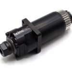
Thread forming tools can look similar to taps, but they produce threads in a very different manner. All images courtesy Walter USA.
Therefore, the production rate and tool cost are not always the main focus when it comes to threading. Sometimes process reliability is the most important consideration. One of three threading processes is commonly performed, and they all have advantages for different scenarios.
Tapping
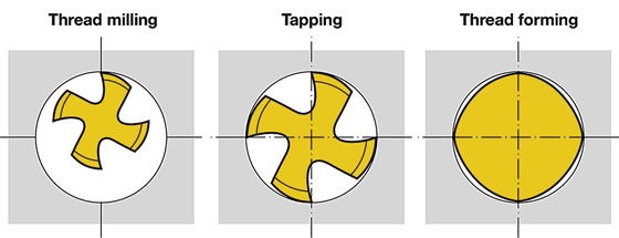
Tapping is the most frequently performed process—estimated at 90 percent—for producing internal threads. The process involves applying a tap tool to cut the workpiece material in the helical configuration required for the threaded hole. The cutting tool must be designed specifically for each thread size and thread style and be fed at a specific feed rate to coincide with thread pitch.
The direction of the feed is only along the Z-axis, which makes programming relatively easy. But, some tool variations should be considered, including number of flutes, chamfer length, tolerance classification, rake angle, clearance angle, flute helix angle and shank standard (the German standards organization DIN or ANSI, for example). Therefore, it can be difficult to find the optimal design for a specific application.
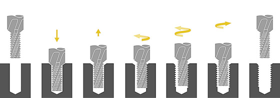
Forming
Thread forming is a process for producing internal threads that has developed quickly over the last 20 years. In this process, the material is pushed, or formed, into the desired shape with a tool that looks similar to a tap, but is completely different in design and functionality. Forming creates a much stronger thread than cutting because it hardens the workpiece by realigning its grain structure while it is in a cold state. In addition, because the workpiece material is not cut, this process produces no chips, eliminating one of the main challenges with tapping—chip control.
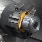
Thread mills have a thread form ground into the tool but use the machine toolpath to control size.
However, this also limits the type of material that can be threaded. The material must be ductile. More brittle materials, such as cast iron, should not be thread-formed.
Milling
Thread milling is the process of cutting material with a rotating tool that has a thread form ground into it. The thread mill is smaller than the diameter of the hole to be threaded, and the machine must interpolate the tool while feeding in the Z-axis direction, creating the helical thread shape.
Typically, the tool must travel 360° to machine a complete thread, but some manufacturers recommend a full 180° to enter the cut and another 180° to exit. So, with the latter scenario, the tool would travel two full revolutions to complete the cut.
Milling threads can make programming the machine more complicated, but because the machine partially controls the exact thread size, adjustments can be made to the overall thread size by altering the program. With tapping and thread forming, this type of adjustment is made by purchasing a different tool.
Thread milling is often performed when machining large threads. But uniquely designed thread mills, called orbital thread mills, can machine threads as small as UNC1-64 and are available as standard products. The hole to be milled is 0.0595 " (1.5113mm) in diameter. Taps, however, are available for producing an M1 thread size, which requires a 0.0295 " (0.7493mm) tap drill.
Process Reliability Comparison
Tapping is a reliable and easy way to machine threads. Achieving consistency, however, requires selecting the correct tap for the job.
Controlling chips is the biggest challenge, particularly in blind-holes. To control them, users must select the correct tap design. This is why most tap manufacturers offer a large selection of different styles of taps and tap geometries.
Another challenge is removing a tap that breaks in the cut. Because the tap head is threaded into the part, it can be difficult to remove the broken piece or pieces. This may require additional machining or even moving the part to a different machine, such as a wire EDM, to extract the broken piece or pieces.
There is less variation among thread formers than cutting taps, which must control chips. Compared to taps, thread formers also have a much larger core diameter, which strengthens the tool.
In the event of a broken tool, a thread former is equally difficult to remove from a hole as a tap, but it is much less likely to break in the first place because of the larger core diameter. However, the range of applications and types of materials and sizes of threads that can be formed is much more limited compared to tapping. Some part designers, and even entire industries, include callouts on their manufacturing prints that prohibit thread forming a part.
This is because thread forming leaves a small gap at the tip of the thread form, sometimes called a "fish mouth" for the way it looks. For example, the medical and food industries do not allow thread forming because this small space can be an area where bacteria grow and is not easily cleaned or sterilized. However, the gap has no impact on thread quality.
Thread milling is the most versatile of the three processes. Only the shape and pitch of the thread is built into the tool, so a thread mill can cut any thread size—as long as the style and pitch is the same. For example, the same tool can mill a 1 "-8-dia. and a 1½ "-8-dia. UN-style thread. Small adjustments can be made to the thread size as well to ensure a certain tolerance specification is met or to compensate for tool wear to maximize tool life.
While the core diameter of a thread mill is smaller than a tap or thread former, the thread milling process does not require a tool with as much strength. With the tool diameter being approximately 70 to 80 percent of the thread diameter, the tool engages much less of the part and less torque is exerted on the tool itself. However, in the event of a broken tool, the smaller diameter also allows the tool to easily be extracted from the part, and the machining process can continue after installing a new thread mill.
Due to the preponderance of threads being tapped, tapping can be considered the reference standard regarding process reliability. Compared to tapping, thread forming is considered to have slightly higher process reliability because it does not produce chips. In addition, a thread former has an inherently larger tool body than a tap, so it is far less likely to break during use. So, for maximum process reliability, consider thread milling. CTE
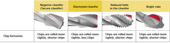
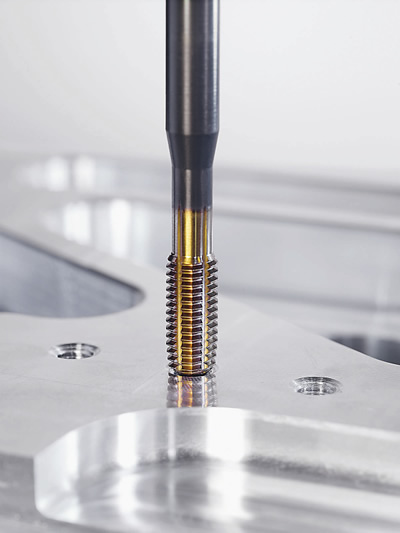
Taps require the correct design for the application to effectively control chips.
Field application I
Recently, Walter USA worked with a die manufacturer in northern Wisconsin to determine if thread milling was a better option than its current tapping method. The tapping process was inconsistent, with erratic tool fracturing and uneven tool life. The P-20 tool-steel part, with a hardness from 33 to 36 HRC, required 30 M30-thread holes with a full thread depth of 2 " (50.8mm). The tap cutting speed was 25 sfm (7.62 m/min.) at 80 rpm, which required 26 seconds to machine the thread.
After some setup and testing, a thread mill matched the cutting time of the tap. Through continued testing, the thread mill achieved a cutting speed of 650 sfm (198.12 m/min.), which reduced the threadmaking time to 19 seconds. Tool life of the thread mill also proved to match that of the tap at 200 pieces, even before compensating for tool wear. Ultimately, the customer was able to machine the part faster at a lower cost per hole and with more consistency and process reliability by switching to thread milling.
Thread formers have a large core diameter, creating a stronger tool than a tap.
Field application II
A fabrication shop in central Illinois was having trouble threading M-8 steel. The print called for a blind-hole to be tapped 17.5mm (0.689 ") deep and through a cross-hole in 17-22 AS cast steel, with a hardness of 35 to 38 HRC. This created chip control issues and sometimes caused a tool to break because the chips were not being properly evacuated.
Walter USA recommended switching from tapping to thread forming. Because the customer was hesitant to change the process, Walter took some sample pieces back to its Technology Center in Waukesha, Wis., to compare tapping and thread forming the feature.
The test results were fairly conclusive; the only hesitation is that it was not possible to run either tool for its full life because only a few sample parts were provided to prove out part quality and process reliability. Testing various tap designs showed some improve- ments. Chip control was enhanced by producing short chips that did not nest together. However, some chips remained in the hole, which then had to be removed via a secondary machining operation. Obviously, no such problem arises when thread forming because the process forms the thread instead of cutting it.
In addition, the thread forming tool showed significantly less wear, giving confidence that, ultimately, tool life would be significantly longer compared to the tap.
The final benefit was the production rate. The tapping feed rate was 10.4 ipm (264.2 mm/min.) while the thread forming feed rate was 23 ipm (584.2 mm/min.). By doubling the feed, thread forming cut the cycle time more than 50 percent. Not only did the customer enhance process reliability with thread forming, but tool life and productivity improved.