Analyzing the options for internal threading allows part makers to efficiently and cost-effectively produce high-quality threaded holes. Presented here are the pros and cons of four key methods of machining internal threads in parts: tapping, milling, turning and grinding.
Tap, Tap, Tap
For many threading applications, taps are effective and popular. “Tapping is the most common because it is typically the lowest cost initially, although not necessarily the most economical overall,” said Cullen Morrison, business development manager, threading for KOMET of America Inc., Schaumburg, Ill., which makes taps and thread mills.
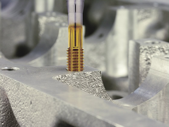
Tapping is a continuous process where material is removed by a spaced sequence of cutting edges that finish the final thread size in one pass. “The tap is built specifically to the size of the thread: the major diameter, minor diameter and pitch diameter,” said Mark Hatch, product director for Emuge Corp., West Boylston, Mass., which offers taps and thread mills. He added that because a tap has to rough and finish in one operation, a high volume of chips must be evacuated efficiently or excessive pressure could be produced, resulting in thread-quality problems or tap damage.
Courtesy of Emuge
Emuge’s MultiTAP-Form tap forms threads in cast aluminum. Form taps compress the workpiece material to generate the desired thread, meaning no chips are created.
Chip control is a big concern when tapping, especially in soft, gummy materials that generate stringy chips. These types of chips can create a bird’s nest around the tap or pack chips in the flutes, which may cause the tap to break in the hole. Aluminum, carbon steels and 300 series stainless steels are probably among the most challenging materials in terms of chip control, noted Cheryl Stewart, applications engineer for tap and thread mill manufacturer OSG Tap & Die Inc., Glendale Heights, Ill.
Taps can be used in almost any material up to 50 HRC, and some toolmakers offer taps that are effective to 65 HRC.
Hole diameter is another consideration, with most end users tapping holes only up to 5⁄8 " in diameter, Morrison said. “With holes above that you run into issues with the machine having enough horsepower to rotate the tap.”
He added that when tapping holes ¼ " and smaller, problems can occur because space for the chips is limited and small tools are relatively weak.
In addition, a tap can machine threads in a hole more than 3 diameters deep. “And that is where a tap is typically much quicker than a single-point thread mill for deep threads,” Morrison said. “As long as you can get the chips out of the hole, you can run a tap as deep as the tool design will let you.”
Because the diameter and pitch are fixed, a tap cannot thread different sized holes. Also, because tapping produces a great deal of contact along the cut and creates a lot of force, a tap can break and become stuck in the hole, possibly generating scrap. Taps also require a high level of lubricity to run efficiently.
Push the Thread
Roll form taps produce internal threads up to about 4 diameters deep by displacing material rather than cutting it. The absence of chips eliminates any worry about creating a bird’s nest, but a maximum workpiece hardness of about 40 HRC is the limit for form tapping. Because the material is displaced, it has to have ductility or elongation properties.
Form taps are typically less than 3⁄4 " in diameter and can go as small as 0.020 "; larger tools produce more friction and require more machine horsepower.
Compared to cutting taps, form taps are more rigid and less prone to breaking. “The pressure on a cutting tap is tangential through the polygon face,” KOMET’s Morrison said. “The pressure on a form tap is toward the center of the tap, so it is much stronger.”
Courtesy of OSG Tap & Die
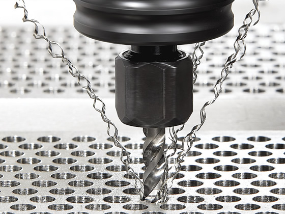
OSG’s EXOPRO CC-SUS spiral tap series for stainless steel features a variable-lead flute design with advanced chip control.
Formed threads are also stronger than cut threads. This is because form taps compress the grain structure to create the thread profile rather than shearing the structure, Emuge’s Hatch explained.
A disadvantage of form taps is they require more machine torque and horsepower and the workholding must be more stable than for cutting taps. “It takes more force to move material than to cut it,” OSG’s Stewart said.
Another limitation is the drilled hole has to be more precise than when cutting threads.
Also, formed threads are not accepted in some industries, including medical and aerospace. “[When form tapping,] there is an imperfection on the minor diameter,” Hatch said. “Aerospace will not allow this cusp [U-shaped profile] on the minor diameter. It doesn’t affect the pull strength, though, so in general-purpose parts, it is not something that would be rejected.”
Hit the Thread Mill
Thread mills use helical interpolation to make internal, as well as external, threads. Most CNC machine tools built in the last 10 to 15 years have this capability.
Solid-carbide and indexable-insert thread mills (steel shank with carbide inserts) are available. Multiple-point thread mills cut the full thread depth in a single revolution around the hole. Single-point thread mills have cutting edges in a single plane and cut one thread at a time. Most thread mills have multiple points.
Thread milling is suitable for materials up to 65 HRC, enhancing versatility. “Typically, one thread mill geometry with one or two different coatings can cover a variety of materials,” Morrison said.
Chip control is typically not an issue with thread milling. “Thread milling is an interrupted cut, which means you always make short, broken chips, regardless of the chipping properties of the material,” Emuge’s Hatch said.
Courtesy of KOMET of America
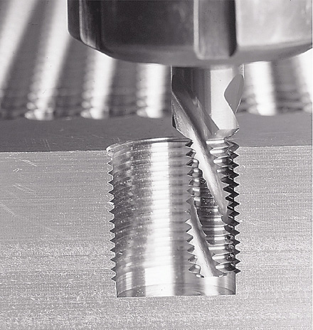
One thread mill can address a range of hole diameters that share a common pitch. Because it has a flat bottom, a thread mill also can machine complete threads near the bottom of a blind-hole.
Thread mills cover a wide application range, with tools available down to 0-80 (0.0600 "cutting diameter) and up to the largest hole diameter. In general, a thread mill’s optimal depth range is limited to about 2.5 diameters deep. “With thread milling, the cutting forces are not balanced,” Hatch said. “When you have a long milling section, because of the high radial forces you can create a lot of side pressure. This can cause problems with deflection and chipping of the cutting edge, and even breakage of smaller tools.”
However, a single-point thread mill can go deeper. “You could go 20 times diameter if you really wanted to,” Morrison said. “You don’t have deflection issues because all of the cutting is on the end. We have a lot of customers that make oil field or big energy parts and need a long-shank thread mill. It is worth it to them to have one tool that can cut multiple threads, even though it is a slower process, rather than invest in a $1,000 tap that is 10 " long.”
Thread milling offers many advantages. One tool can address a range of hole diameters that share a common pitch. The single-point style can do multiple pitches and multiple diameters.
Also, a single tool geometry can mill threads in blind- and through-holes and can produce right- and left-hand threads. Because it has a flat bottom, a thread mill is also able to machine complete threads near the bottom of a blind-hole, and tool breakage isn’t likely to produce scrap. Finally, a thread mill can be combined with other holemaking tools into a single tool, such as one that can drill, chamfer and thread.
However, the cycle time is usually longer than with a tap. “Because a thread mill requires a special program, some users may shy away from using them,” OSG’s Stewart said. “However, it is a simple program that can be done with many NC programs.”
Some companies still prefer tapping because they want to limit operator involvement. Thread milling involves compensations or adjustments by the operator at the machine. “As the tool becomes smaller through normal wear, the operator needs to introduce cutter compensation to adjust for that wear to maintain proper size,” Hatch said. “It is a function of the operator measuring the tolerance of the thread and then making adjustments based on the wear.
“You can’t change the size of the tap. It is ground to the dimensions of the thread,” he continued. “The operator just periodically does an inspection with the gage and, when the gage fails, the tap is removed.”
Turning Away
Another way to make internal threads is thread turning, performed with an indexable-insert or solid miniature boring-type tool on a multiaxis machine or lathe. Single-point or multiple-tooth inserts can be applied. Multiple-tooth inserts feature multiple teeth on each cutting edge, with each subsequent tooth cutting deeper than the previous tooth, reducing the number of passes required to produce a thread.
However, multitooth inserts are more expensive. “High-production runs would benefit from using multitooth inserts, but for low-volume runs they might not be advantageous,” said Jeff Dei, president of Carmex Precision Tools LLC, Richfield, Wis., which makes thread turning and thread milling tools.
Courtesy of Carmex Precision Tools
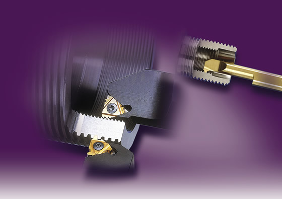
Carmex’s thread turning inserts can create both internal and external threads. Solid boring-type tools can also be used.
Courtesy of Vargus USA
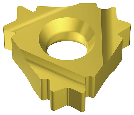
The V6 thread turning insert from Vargus has a six-cutting-corner system. Inserts are available for making partial- and full-profile threads.
Also, multitooth inserts cannot get directly up to a shoulder. “Depending on the pitch, from your first tooth to your last tooth, there is maybe 0.120 ",” said Mike Trimble, product manager for Vargus USA, Janesville, Wis., which also offers thread turning and thread milling tools. “You have to clear the last tooth out the back of the thread to get a complete thread; it has to go about 0.120 ". So if the threading is up to a shoulder, you can’t get that deep because there is not enough room.”
When thread turning with a single-point tool, the user can apply a full-profile or partial-profile insert. (Multitooth inserts are full-profile only.) The full-profile insert forms a complete thread profile, including the crest (the insert cuts the minor diameter). With this style, every thread pitch requires a separate insert.
The full-profile insert produces a stronger, more accurate thread than a partial-profile one and does so in fewer passes. This is because the insert creates the major, minor and pitch diameters at the same time, Trimble said.
The partial-profile insert cuts the thread without cresting the thread (it doesn’t cut the minor diameter). A partial-profile insert has only one point, allowing it to produce a range of thread pitches by penetrating to different depths. “It has a very sharp nose radius, so with a coarser pitch thread you lose thread strength and it may take longer to make the thread,” Dei said.
Thread turning with an indexable-type tool can be performed from the largest hole diameter down to a 0.240 " bore. Below that requires a solid-carbide tool, which can thread down to about a 0.050 " bore diameter.
Regarding large holes, Vargus has threaded a hole 3 ' in diameter. Trimble said: “This was on a vertical turret lathe that was about 100 years old. There was no other way to do it but turn it. There is no helical interpolation on a machine like that.”
Thread turning is appropriate for holes up to 3 diameters deep when using a steel shank and 4 and even 5 diameters deep with a carbide shank.
Thread turning is performed in a variety of materials. “We thread turn up to 50 HRC every day,” Trimble said. “We also thread turn in exotic materials, such as Hastelloy and Inconel, but you will lose tool life because the material is very hard or abrasive.”
Chip control is a big issue with internal thread turning, especially in blind-holes. Users can compensate with the insert geometry, the infeed method (radial, flank, modified flank or alternating flank) used to evacuate chips or by using the reverse helix method, where instead of threading toward the spindle, threading is done away from the spindle to evacuate chips, Trimble explained.
“The infeed method used depends on the application, but in most cases, if you go with the modified radial infeed, you are not going to hurt anything,” Trimble said. “You can always use it as your default. But in 99 percent of machine tools, if you don’t change one of the parameters in the program, you are going to get a radial infeed.”
How does a part manufacturer decide whether to tap, mill or turn? “It is going to be a trial process,” Dei replied. “If one isn’t yielding satisfactory results, you will have to try the other option. They all have their advantages and disadvantages. The biggest thing is when looking at the part to thread, look at what machines you have and figure out the cost of tooling, cycle times and tool life.” CTE
Grinding threads for tight-tolerance parts
Thread grinding is an accurate way to produce internal threads and is an effective choice for tight-tolerance parts. A wide range of internal threads, grooves, ball tracks and other forms can be ground on one machine. Typical parts ground on an internal thread grinder include thread gages and nuts for roller, lead and ball screws.
Internal thread grinding is typically performed on a dedicated machine. To grind threads with an accurate profile, the machine generally must have the wheel set at the helix angle of the thread. This requires a rotary axis, which the vast majority of universal grinders do not have. While external threads can sometimes be ground with a multiple-rib wheel plunged straight into the part, where the wheel profile has been modified to correct for the helical shape (A-axis parallel grinding), internal thread grinding requires a single-rib wheel with the A-axis set on the helix.
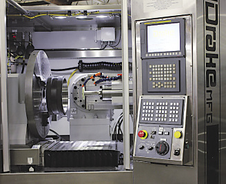
Courtesy of Drake Manufacturing Services
Drake’s internal thread grinder machines a thread ring gage.
The typical ID for economical thread grinding is from 0.40 " to 21 ". The rule of thumb for threading deep holes is to have a 7:1 quill-length-to-quill-diameter ratio, according to grinding machine builder Drake Manufacturing Services Co., Warren, Ohio. The challenge to grinding threads in deep holes is the helix angle vs. hole diameter. As the thread length increases and the hole diameter decreases, it is difficult to grind parts with large helix angles. There are limits where the grinding quill will hit the part.
Chip control issues with internal thread grinding include coolant application for flushing the grind area. Again, with limited space it is difficult to apply coolant at the grinding zone and in the direction of the wheel rotation and not be in the way of the wheel and quill entering into a small hole.
Internal thread grinding is extremely accurate. The grinding wheel can be dressed precisely, and, once that form is in the wheel, the wheel can be quickly redressed as required, according to Drake. Also, thread grinding can enhance productivity. The wheel can be redressed to make a different thread form instead of having to change to a different one.
According to Drake, an internal grinding machine needs several features to perform well. These include stiffness, thermal stability, precise axis movements, accurate closed-loop position feedback and precise, temperature-controlled spindles.
—S. Woods
Contributors
Carmex Precision Tools LLC
(262) 628-5030
www.carmexusa.com
Drake Manufacturing Services Co.
(330) 847-7291
www.drakemfg.com
Emuge Corp.
(800) 323-3013
www.emuge.com
KOMET of America Inc.
(847) 923-8400
www.komet.com
OSG Tap & Die Inc.
(800) 837-2223
www.osgtool.com
Vargus USA
(800) 828-8765
www.vargususa.com
Related Glossary Terms
- abrasive
abrasive
Substance used for grinding, honing, lapping, superfinishing and polishing. Examples include garnet, emery, corundum, silicon carbide, cubic boron nitride and diamond in various grit sizes.
- blind-hole
blind-hole
Hole or cavity cut in a solid shape that does not connect with other holes or exit through the workpiece.
- carbon steels
carbon steels
Known as unalloyed steels and plain carbon steels. Contains, in addition to iron and carbon, manganese, phosphorus and sulfur. Characterized as low carbon, medium carbon, high carbon and free machining.
- computer numerical control ( CNC)
computer numerical control ( CNC)
Microprocessor-based controller dedicated to a machine tool that permits the creation or modification of parts. Programmed numerical control activates the machine’s servos and spindle drives and controls the various machining operations. See DNC, direct numerical control; NC, numerical control.
- coolant
coolant
Fluid that reduces temperature buildup at the tool/workpiece interface during machining. Normally takes the form of a liquid such as soluble or chemical mixtures (semisynthetic, synthetic) but can be pressurized air or other gas. Because of water’s ability to absorb great quantities of heat, it is widely used as a coolant and vehicle for various cutting compounds, with the water-to-compound ratio varying with the machining task. See cutting fluid; semisynthetic cutting fluid; soluble-oil cutting fluid; synthetic cutting fluid.
- cutter compensation
cutter compensation
Feature that allows the operator to compensate for tool diameter, length, deflection and radius during a programmed machining cycle.
- ductility
ductility
Ability of a material to be bent, formed or stretched without rupturing. Measured by elongation or reduction of area in a tensile test or by other means.
- elongation
elongation
In tensile testing, the increase in the gage length, measured after fracture of the specimen within the gage length, usually expressed as a percentage of the original gage length.
- flat ( screw flat)
flat ( screw flat)
Flat surface machined into the shank of a cutting tool for enhanced holding of the tool.
- flutes
flutes
Grooves and spaces in the body of a tool that permit chip removal from, and cutting-fluid application to, the point of cut.
- gang cutting ( milling)
gang cutting ( milling)
Machining with several cutters mounted on a single arbor, generally for simultaneous cutting.
- grinding
grinding
Machining operation in which material is removed from the workpiece by a powered abrasive wheel, stone, belt, paste, sheet, compound, slurry, etc. Takes various forms: surface grinding (creates flat and/or squared surfaces); cylindrical grinding (for external cylindrical and tapered shapes, fillets, undercuts, etc.); centerless grinding; chamfering; thread and form grinding; tool and cutter grinding; offhand grinding; lapping and polishing (grinding with extremely fine grits to create ultrasmooth surfaces); honing; and disc grinding.
- grinding machine
grinding machine
Powers a grinding wheel or other abrasive tool for the purpose of removing metal and finishing workpieces to close tolerances. Provides smooth, square, parallel and accurate workpiece surfaces. When ultrasmooth surfaces and finishes on the order of microns are required, lapping and honing machines (precision grinders that run abrasives with extremely fine, uniform grits) are used. In its “finishing” role, the grinder is perhaps the most widely used machine tool. Various styles are available: bench and pedestal grinders for sharpening lathe bits and drills; surface grinders for producing square, parallel, smooth and accurate parts; cylindrical and centerless grinders; center-hole grinders; form grinders; facemill and endmill grinders; gear-cutting grinders; jig grinders; abrasive belt (backstand, swing-frame, belt-roll) grinders; tool and cutter grinders for sharpening and resharpening cutting tools; carbide grinders; hand-held die grinders; and abrasive cutoff saws.
- grinding wheel
grinding wheel
Wheel formed from abrasive material mixed in a suitable matrix. Takes a variety of shapes but falls into two basic categories: one that cuts on its periphery, as in reciprocating grinding, and one that cuts on its side or face, as in tool and cutter grinding.
- hardness
hardness
Hardness is a measure of the resistance of a material to surface indentation or abrasion. There is no absolute scale for hardness. In order to express hardness quantitatively, each type of test has its own scale, which defines hardness. Indentation hardness obtained through static methods is measured by Brinell, Rockwell, Vickers and Knoop tests. Hardness without indentation is measured by a dynamic method, known as the Scleroscope test.
- helix angle
helix angle
Angle that the tool’s leading edge makes with the plane of its centerline.
- inner diameter ( ID)
inner diameter ( ID)
Dimension that defines the inside diameter of a cavity or hole. See OD, outer diameter.
- interpolation
interpolation
Process of generating a sufficient number of positioning commands for the servomotors driving the machine tool so the path of the tool closely approximates the ideal path. See CNC, computer numerical control; NC, numerical control.
- interrupted cut
interrupted cut
Cutting tool repeatedly enters and exits the work. Subjects tool to shock loading, making tool toughness, impact strength and flexibility vital. Closely associated with milling operations. See shock loading.
- lathe
lathe
Turning machine capable of sawing, milling, grinding, gear-cutting, drilling, reaming, boring, threading, facing, chamfering, grooving, knurling, spinning, parting, necking, taper-cutting, and cam- and eccentric-cutting, as well as step- and straight-turning. Comes in a variety of forms, ranging from manual to semiautomatic to fully automatic, with major types being engine lathes, turning and contouring lathes, turret lathes and numerical-control lathes. The engine lathe consists of a headstock and spindle, tailstock, bed, carriage (complete with apron) and cross slides. Features include gear- (speed) and feed-selector levers, toolpost, compound rest, lead screw and reversing lead screw, threading dial and rapid-traverse lever. Special lathe types include through-the-spindle, camshaft and crankshaft, brake drum and rotor, spinning and gun-barrel machines. Toolroom and bench lathes are used for precision work; the former for tool-and-die work and similar tasks, the latter for small workpieces (instruments, watches), normally without a power feed. Models are typically designated according to their “swing,” or the largest-diameter workpiece that can be rotated; bed length, or the distance between centers; and horsepower generated. See turning machine.
- lubricity
lubricity
Measure of the relative efficiency with which a cutting fluid or lubricant reduces friction between surfaces.
- milling
milling
Machining operation in which metal or other material is removed by applying power to a rotating cutter. In vertical milling, the cutting tool is mounted vertically on the spindle. In horizontal milling, the cutting tool is mounted horizontally, either directly on the spindle or on an arbor. Horizontal milling is further broken down into conventional milling, where the cutter rotates opposite the direction of feed, or “up” into the workpiece; and climb milling, where the cutter rotates in the direction of feed, or “down” into the workpiece. Milling operations include plane or surface milling, endmilling, facemilling, angle milling, form milling and profiling.
- milling machine ( mill)
milling machine ( mill)
Runs endmills and arbor-mounted milling cutters. Features include a head with a spindle that drives the cutters; a column, knee and table that provide motion in the three Cartesian axes; and a base that supports the components and houses the cutting-fluid pump and reservoir. The work is mounted on the table and fed into the rotating cutter or endmill to accomplish the milling steps; vertical milling machines also feed endmills into the work by means of a spindle-mounted quill. Models range from small manual machines to big bed-type and duplex mills. All take one of three basic forms: vertical, horizontal or convertible horizontal/vertical. Vertical machines may be knee-type (the table is mounted on a knee that can be elevated) or bed-type (the table is securely supported and only moves horizontally). In general, horizontal machines are bigger and more powerful, while vertical machines are lighter but more versatile and easier to set up and operate.
- numerical control ( NC)
numerical control ( NC)
Any controlled equipment that allows an operator to program its movement by entering a series of coded numbers and symbols. See CNC, computer numerical control; DNC, direct numerical control.
- parallel
parallel
Strip or block of precision-ground stock used to elevate a workpiece, while keeping it parallel to the worktable, to prevent cutter/table contact.
- pitch
pitch
1. On a saw blade, the number of teeth per inch. 2. In threading, the number of threads per inch.
- shank
shank
Main body of a tool; the portion of a drill or similar end-held tool that fits into a collet, chuck or similar mounting device.
- stainless steels
stainless steels
Stainless steels possess high strength, heat resistance, excellent workability and erosion resistance. Four general classes have been developed to cover a range of mechanical and physical properties for particular applications. The four classes are: the austenitic types of the chromium-nickel-manganese 200 series and the chromium-nickel 300 series; the martensitic types of the chromium, hardenable 400 series; the chromium, nonhardenable 400-series ferritic types; and the precipitation-hardening type of chromium-nickel alloys with additional elements that are hardenable by solution treating and aging.
- stiffness
stiffness
1. Ability of a material or part to resist elastic deflection. 2. The rate of stress with respect to strain; the greater the stress required to produce a given strain, the stiffer the material is said to be. See dynamic stiffness; static stiffness.
- tap
tap
Cylindrical tool that cuts internal threads and has flutes to remove chips and carry tapping fluid to the point of cut. Normally used on a drill press or tapping machine but also may be operated manually. See tapping.
- tapping
tapping
Machining operation in which a tap, with teeth on its periphery, cuts internal threads in a predrilled hole having a smaller diameter than the tap diameter. Threads are formed by a combined rotary and axial-relative motion between tap and workpiece. See tap.
- thread grinder
thread grinder
Typically a form grinder as well as a thread grinder, this machine differs from other grinders in that precision gears and leadscrews ensure a precise traverse to impart the correct lead to a thread.
- threading
threading
Process of both external (e.g., thread milling) and internal (e.g., tapping, thread milling) cutting, turning and rolling of threads into particular material. Standardized specifications are available to determine the desired results of the threading process. Numerous thread-series designations are written for specific applications. Threading often is performed on a lathe. Specifications such as thread height are critical in determining the strength of the threads. The material used is taken into consideration in determining the expected results of any particular application for that threaded piece. In external threading, a calculated depth is required as well as a particular angle to the cut. To perform internal threading, the exact diameter to bore the hole is critical before threading. The threads are distinguished from one another by the amount of tolerance and/or allowance that is specified. See turning.
- tolerance
tolerance
Minimum and maximum amount a workpiece dimension is allowed to vary from a set standard and still be acceptable.
- turning
turning
Workpiece is held in a chuck, mounted on a face plate or secured between centers and rotated while a cutting tool, normally a single-point tool, is fed into it along its periphery or across its end or face. Takes the form of straight turning (cutting along the periphery of the workpiece); taper turning (creating a taper); step turning (turning different-size diameters on the same work); chamfering (beveling an edge or shoulder); facing (cutting on an end); turning threads (usually external but can be internal); roughing (high-volume metal removal); and finishing (final light cuts). Performed on lathes, turning centers, chucking machines, automatic screw machines and similar machines.
- turret lathe
turret lathe
Differs from engine lathe in that the normal compound rest is replaced by pivoting, multitool turrets mounted on the cross slide and tailstock. See lathe.