END USER: Emhart Glass Manufacturing Inc., (607) 734-3671, www.emhartglass.com.
CHALLENGE: Increase productivity when parting off a component.
SOLUTION: A new parting and grooving tool that practically tripled machining parameters.
SOLUTION PROVIDER: Sandvik Coromant Co., (800) SANDVIK, www.sandvik.coromant.com/us.
Glass containers and bottles are so ubiquitous that most people have used containers that were formed and inspected on a BUCHER Emhart Glass machine, according to the company. Providing glass containers for more than a century, Bucher Emhart Glass says it developed the industry-standard Individual Section (IS) machine, a glass container forming device. This machine has a bank of five to 20 identical sections, each of which contains a complete set of mechanisms for making different-sized formed glass containers—most destined for the medical, scientific, or food and beverage industries.
In glass manufacturing, inspection and defect analysis is a critical step. To ensure Bucher Emhart Glass continued to provide top quality glass containers, the company purchased Powers Manufacturing, Elmira, N.Y., in 1982. Powers was a supplier of cold-end inspection equipment.
The Elmira outpost of BUCHER Emhart Glass, which still designs, machines, assembles and ships complex inspection machines, employs about 140 people, with a machine shop and assembly all under one roof. The machine shop portion of the facility occupies roughly 12,000 sq. ft., with 25 employees covering two shifts.
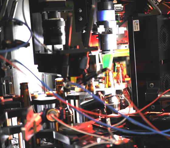
Emhart Glass’ empty bottle inspection system uses a camera to look through the top of the bottle and take an image of the bottom. That image is used to detect flaws. The machined components in this parting-off application are used in a device that rotates the bottle within the machine during testing.
The shop has seven vertical machines, two horizontals, three 3-axis-lathes and a 7-axis-lathe. The brand mix includes a Mazak mill and turning machine, three Hardinge lathes, two Haas machines, one Komo, and a Bridgeport vertical. Primary materials include Ledloy 12L14, which tends to be softer and easier machine than other materials, and aluminum, bronze and stainless steel, which tend to be tougher.
The workflow at the Emhart machine shop is punctuated by numerous short-run jobs. To limit downtime, this schedule requires operator flexibility as frequent changeovers put increased pressure on the machines and tooling to run as quickly as possible. These short-run jobs require optimal cutting speeds and long tool life in order for the shop to stay productive.
“We’ve been using Sandvik Coromant tooling since the mid-1990s, mostly for milling and turning,” said David Turk, manufacturing CNC engineer at Emhart Glass. “Sandvik Coromant is our dominant insert and toolholder supplier. We have a few others, but they account for probably 80 to 85 percent of our indexable carbide. We have a good relationship with our local tool supplier, One Time Tool, and they suggested we try Sandvik Coromant—we did and we’ve been using them ever since.”
Although Turk was already using Sandvik Coromant tooling for other operations, he was not convinced to change the current operation for parting-off components on a lathe. Sticking with a process and a product he has used for years, he kept an eye out for products offering significant improvement, but nothing he tested was that much better. Parting-off is not a rarely-used operation by Emhart; it is required for several components.
As it’s frequently the final stage of the machining process, parting-off is a crucial step. Between machine setups, programming, and time already spent making chips, operators and machines have invested quite a bit into machining the component by the time parting-off is considered. Parts have already been turned, tapped, drilled, grooved and finished prior to parting-off. Scrapping a part after such an investment in time and machine capacity is simply not an option at this point. So, sticking with the process that Turk and others at Emhart believed to be the safest bet was what they were going to do unless something could radically change their productivity levels.
Warranting a switch
“We had tried different inserts, different suppliers, even some inserts from Sandvik Coromant—we just didn’t see enough results to warrant any changes,” Turk said. “Because we do a lot of short-run jobs, and there already is a lot of setting up and making programming changes, we wanted to see something where we could get a lot of bang for our buck upon making the switch. Over the years we saw some marginal increases in speed and efficiency with other inserts and tooling, but not enough to push our hand to make a change.”
But even though Turk hadn’t been sufficiently wowed by any other parting-off tooling on the market, the operator, Tom Waite, again asked Turk to keep an eye out for new tooling for the parting-off operation in the fall of 2013. Meanwhile, Jim Pappas, sales engineer at Sandvik Coromant, had just completed training on the company’s new CoroCut QD parting and grooving tool. The timing was serendipitous for Pappas to give Turk a ring.
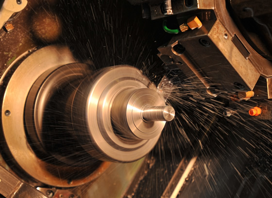
Component being machined here is the one used in bottle rotation (as in the previous image). The material is 3½"-dia. 12L14 steel. With CoroCut QD, EmhartGlass machines the components at 600 sfm and 0.007"/rev. With the previous tool, Emhart had to run at 220 sfm and 0.002"/rev.
Coolant coming out of the tool tip, at the cutting surface, which is a departure from the previous setup, where coolant was delivered from above.
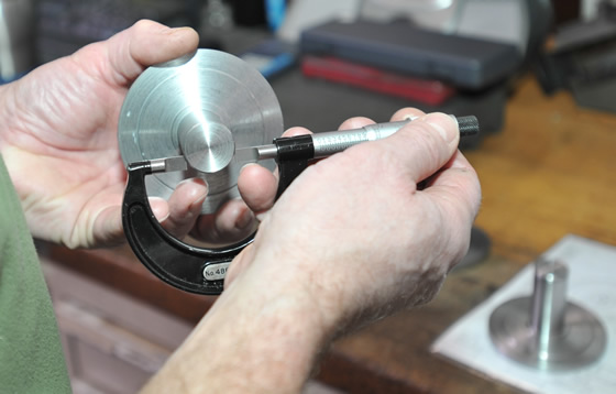
Tom Waite measures the snap ring groove diameter in the machined component.
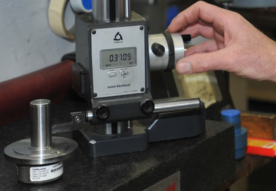
Turk uses a height gage to judge thickness of the parted-off component to the side diameter. The new CoroCut QD cuts as accurately as or more accurately than the previous tool, while cutting much faster.
“We were talking about new product releases and got to the parting and grooving tooling. I mentioned Tom’s request for these kinds of tools, and the light bulb went on for both of us,” Turk said. “Jim came in to the machine shop with the CoroCut QD, gave us the parameters, got a big piece of stock and started testing. Right out of the box we were impressed by the way the chips came off that thing—it was amazing.”
Out-of-the-box improvements
From day one, Turk got the results he had been searching for in his parting off applications. With CoroCut QD, he was tripling the chips per revolution and tripling the surface feet. Material was moving so fast that they actually had to pump the brakes a bit, slowing the spindle speed down so as to optimize tool life, which Turk says has also been notable.
“We had probably been going through about five inserts per week before; now that’s down to about one per week,” Turk says. “As for speed, we were originally doing about 220 sfm, doing 0.002 ipr, and now we’re at 600 sfm and 0.007 ipr, so that’s a dramatic increase.”
Moving more material directly translates to getting more parts done. Timing is always dependent on the diameter of the turned component, but for a piece of 3" stock, Waite and Turk have gone from a 20-second part off time to about a 6-to 8-second part off time. By taking a conservative margin of 10 seconds per part (due to changes in diameter), Turk’s quick math says that the CoroCut QD is probably saving 15 minutes per shift, which equates to a half hour per day. Extrapolating that figure out to the year, that’s125 hours saved.
But all the speed in the world would be useless without accuracy. Guaranteeing repeatable straight cuts is just as important.
“The quality of the cut is there, plus it’s nice and straight. When parting off, you can sometimes get a concave or convex taper; bellow in or bellow out,” Turk says. “We used an indicator, a measuring instrument designed to check for taper, to make sure the blade was running perpendicular to the component’s surface. Once we were calibrated, we were good from there.”
With all of the major tests showing dramatic improvement in productivity while maintaining the highest degree of accuracy, Turk was impressed. But, as the machine operator, Waite would also require some convincing. The crucible here happened on an operation where the lathe’s turret configuration required running the CoroCut QD right side up instead of upside down.
“Common protocol on turning machines is to face the cutting surface upside down, so gravity will assist with chip removal. Without gravity’s assistance, chips can become choked in comparatively narrow parting and grooving applications, which can be 3/16"(5mm); that’s a narrow slot we’ve got to evacuate chips from,” Turk said. “Tom was quick to mention how impressed he was with the way the coolant forces the chips out of the groove—even when cutting right side up.”
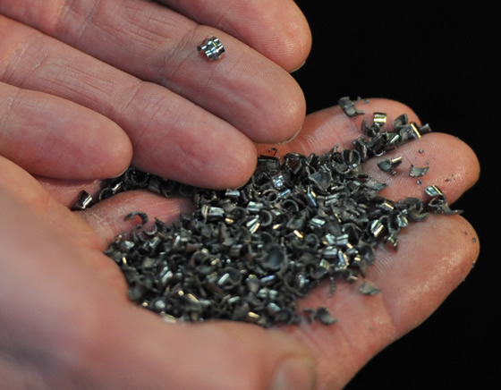
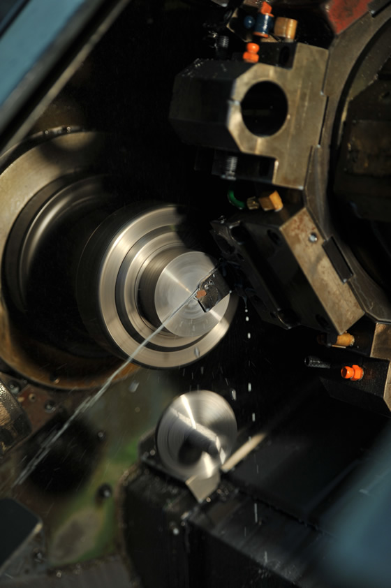
Cutting right side up, Emhart Glass produces these small chips, instead of long, stringy ones.
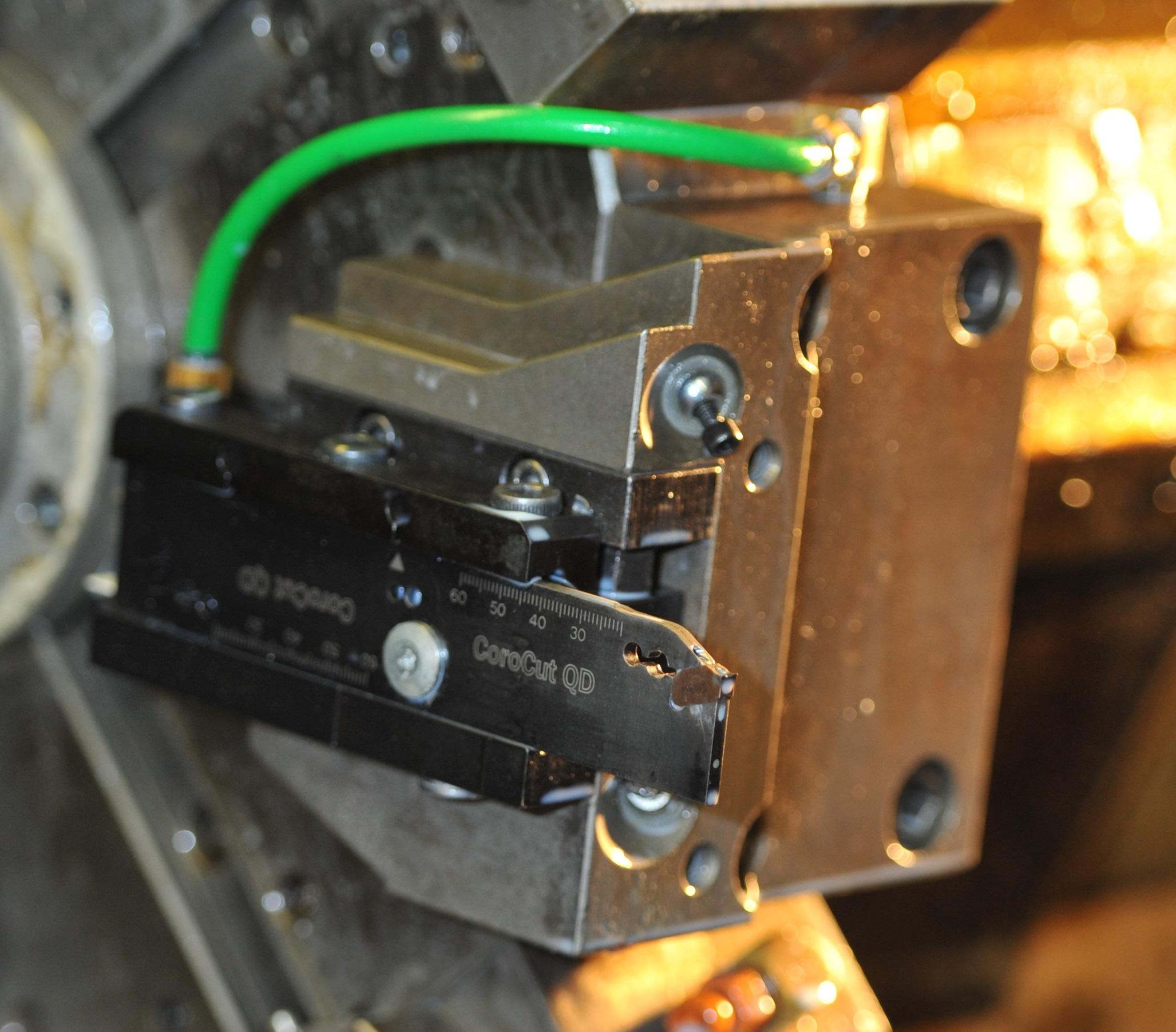
The tool in the turret reveals how it is plumbed with the green coolant hose, which then delivers the coolant to the cutting surface.
According to Turk, the internal coolant which flows through the tool to transport a steady stream right at the cutting edge helps with both the longevity of the tool and the chip evacuation. The previous parting-off cutter had relied on an external coolant line which didn’t provide the same precise coolant delivery.
The instinct to stick with a system that works is usually a good one, especially if nothing is that much better than a current process. But sometimes staying with a tried-and-true process prevents shops from learning about new solutions that could provide them with a giant technical leap forward. Turk and Waite are prime examples of engineers and operators who were patient enough to wait for the right product at the right time, and experienced enough to make a change after discovering the next big thing in parting off applications.
Five tips to improve your parting-off operation
Scott Lewis, Sandvik Coromant product and application specialist, describes five “secrets” that will maximize productivity in parting-off operations.
1. Reduce the feed when you’re approaching the center. When you get to 0.080" (2mm) from center, begin backing off the feed by as much as 75 percent. As you get towards the center, the diameter shrinks, and the machine has to increase the rpms to compensate. But the machine can only compensate so much, and eventually, the rpms will drop.
2. Cease coolant flow when rpms decrease. Coolant helps with chip control, but through-coolant design may actually do its job too well in some cases when near the center. If the coolant is keeping the temperature at the cutting surface too low, it will create a built up edge that will shorten insert life.
3. Keep center height within reason. Don’t get outside of ±0.004" from center height or you risk anything from chatter to total insert failure. When your setup is either too far above or too far below center, you’re likely losing valuable insert life.
4. Keep overhangs short. CoroCut QD allows you to push boundaries of the usual rule of thumb, which says don’t go more than 8-10 x insert width. But if you can, keep overhangs short to make sure you’re always cutting with good rigidity and good security.
5. Stop feed just before center. Stop feed completely just before you hit zero point and let gravity/component weight do the work. If you feed the cutting tool straight to the center, or even worse, through the center, you’re exposing the tool to less than ideal conditions—rpms, for instance, are zero at center. The insert can be hit by the part falling off, causing edge damage. Or, if there’s a sub spindle, an operator can twist it off the part and pull it away from the feed bar.
Related Glossary Terms
- backing
backing
1. Flexible portion of a bandsaw blade. 2. Support material behind the cutting edge of a tool. 3. Base material for coated abrasives.
- chatter
chatter
Condition of vibration involving the machine, workpiece and cutting tool. Once this condition arises, it is often self-sustaining until the problem is corrected. Chatter can be identified when lines or grooves appear at regular intervals in the workpiece. These lines or grooves are caused by the teeth of the cutter as they vibrate in and out of the workpiece and their spacing depends on the frequency of vibration.
- computer numerical control ( CNC)
computer numerical control ( CNC)
Microprocessor-based controller dedicated to a machine tool that permits the creation or modification of parts. Programmed numerical control activates the machine’s servos and spindle drives and controls the various machining operations. See DNC, direct numerical control; NC, numerical control.
- coolant
coolant
Fluid that reduces temperature buildup at the tool/workpiece interface during machining. Normally takes the form of a liquid such as soluble or chemical mixtures (semisynthetic, synthetic) but can be pressurized air or other gas. Because of water’s ability to absorb great quantities of heat, it is widely used as a coolant and vehicle for various cutting compounds, with the water-to-compound ratio varying with the machining task. See cutting fluid; semisynthetic cutting fluid; soluble-oil cutting fluid; synthetic cutting fluid.
- feed
feed
Rate of change of position of the tool as a whole, relative to the workpiece while cutting.
- gang cutting ( milling)
gang cutting ( milling)
Machining with several cutters mounted on a single arbor, generally for simultaneous cutting.
- grooving
grooving
Machining grooves and shallow channels. Example: grooving ball-bearing raceways. Typically performed by tools that are capable of light cuts at high feed rates. Imparts high-quality finish.
- lathe
lathe
Turning machine capable of sawing, milling, grinding, gear-cutting, drilling, reaming, boring, threading, facing, chamfering, grooving, knurling, spinning, parting, necking, taper-cutting, and cam- and eccentric-cutting, as well as step- and straight-turning. Comes in a variety of forms, ranging from manual to semiautomatic to fully automatic, with major types being engine lathes, turning and contouring lathes, turret lathes and numerical-control lathes. The engine lathe consists of a headstock and spindle, tailstock, bed, carriage (complete with apron) and cross slides. Features include gear- (speed) and feed-selector levers, toolpost, compound rest, lead screw and reversing lead screw, threading dial and rapid-traverse lever. Special lathe types include through-the-spindle, camshaft and crankshaft, brake drum and rotor, spinning and gun-barrel machines. Toolroom and bench lathes are used for precision work; the former for tool-and-die work and similar tasks, the latter for small workpieces (instruments, watches), normally without a power feed. Models are typically designated according to their “swing,” or the largest-diameter workpiece that can be rotated; bed length, or the distance between centers; and horsepower generated. See turning machine.
- milling
milling
Machining operation in which metal or other material is removed by applying power to a rotating cutter. In vertical milling, the cutting tool is mounted vertically on the spindle. In horizontal milling, the cutting tool is mounted horizontally, either directly on the spindle or on an arbor. Horizontal milling is further broken down into conventional milling, where the cutter rotates opposite the direction of feed, or “up” into the workpiece; and climb milling, where the cutter rotates in the direction of feed, or “down” into the workpiece. Milling operations include plane or surface milling, endmilling, facemilling, angle milling, form milling and profiling.
- milling machine ( mill)
milling machine ( mill)
Runs endmills and arbor-mounted milling cutters. Features include a head with a spindle that drives the cutters; a column, knee and table that provide motion in the three Cartesian axes; and a base that supports the components and houses the cutting-fluid pump and reservoir. The work is mounted on the table and fed into the rotating cutter or endmill to accomplish the milling steps; vertical milling machines also feed endmills into the work by means of a spindle-mounted quill. Models range from small manual machines to big bed-type and duplex mills. All take one of three basic forms: vertical, horizontal or convertible horizontal/vertical. Vertical machines may be knee-type (the table is mounted on a knee that can be elevated) or bed-type (the table is securely supported and only moves horizontally). In general, horizontal machines are bigger and more powerful, while vertical machines are lighter but more versatile and easier to set up and operate.
- parting
parting
When used in lathe or screw-machine operations, this process separates a completed part from chuck-held or collet-fed stock by means of a very narrow, flat-end cutting, or parting, tool.
- sawing machine ( saw)
sawing machine ( saw)
Machine designed to use a serrated-tooth blade to cut metal or other material. Comes in a wide variety of styles but takes one of four basic forms: hacksaw (a simple, rugged machine that uses a reciprocating motion to part metal or other material); cold or circular saw (powers a circular blade that cuts structural materials); bandsaw (runs an endless band; the two basic types are cutoff and contour band machines, which cut intricate contours and shapes); and abrasive cutoff saw (similar in appearance to the cold saw, but uses an abrasive disc that rotates at high speeds rather than a blade with serrated teeth).
- toolholder
toolholder
Secures a cutting tool during a machining operation. Basic types include block, cartridge, chuck, collet, fixed, modular, quick-change and rotating.
- turning
turning
Workpiece is held in a chuck, mounted on a face plate or secured between centers and rotated while a cutting tool, normally a single-point tool, is fed into it along its periphery or across its end or face. Takes the form of straight turning (cutting along the periphery of the workpiece); taper turning (creating a taper); step turning (turning different-size diameters on the same work); chamfering (beveling an edge or shoulder); facing (cutting on an end); turning threads (usually external but can be internal); roughing (high-volume metal removal); and finishing (final light cuts). Performed on lathes, turning centers, chucking machines, automatic screw machines and similar machines.
- turning machine
turning machine
Any machine that rotates a workpiece while feeding a cutting tool into it. See lathe.
Author

Alan holds a bachelor’s degree in journalism from Southern Illinois University Carbondale. Including his 20 years at CTE, Alan has more than 30 years of trade journalism experience.


