END USER: Machine Tool & Gear Inc., (989) 743-3936, www.machinetoolgear.com.
CHALLENGE: Overcome excessive tool wear and poor surface finishes when machining flats on a steel truck shaft.
SOLUTION: A milling tool that exerts all cutting forces downward and cuts freely.
SOLUTION PROVIDER: Horn USA Inc., (888) 818-HORN, www.hornusa.com.
The last thing a tool distributor wants is for a customer to return an expensive product because it can’t produce acceptable parts. PF Markey Inc., headquartered in Saginaw, Mich., faced this possibility after the distributor sold two 90° milling heads that cost about $10,000 each to Machine Tool & Gear Inc., Owosso, Mich. The heads, which attach to the machine tool spindle and accept a cutting tool, were to machine shafts on a Mori Seiki NH 4000 horizontal machining center at the company’s plant in Corunna, Mich.
MT&G purchased the heads when a new truck shaft design included two flat areas 180° apart that must be machined at 90° from other operations, because adding a machine and fixtures to perform the additional process would have been cost-prohibitive, according to MT&G Manufacturing Engineer Jeff Ochodnicky. However, MT&G experienced excessive tool wear and poor surface finishes when cutting with the heads—even after experimenting with numerous machining parameters.
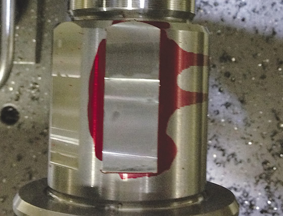
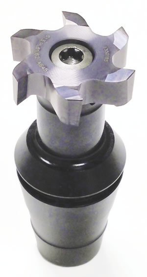
The Mini Mill tool (below) from Horn USA enables Machine Tool & Gear to achieve a 15 to 20 µin. Ra surface finish when milling flats in a steel truck shaft.
That’s when Brett Kischnick, applications engineer for toolmaker Horn USA Inc., Franklin, Tenn., got a call. “Phil Horn, at the distributor, said, ‘I don’t want them to return these heads’ and asked if I could do anything to help.” Kischnick replied, “Let me at it.”
The challenge was milling flats 1.500 " (38.1mm) long and 0.060 " (1.524mm) deep on a steel shaft with a cutting tool 0.854 " (21.692mm) in diameter that hangs more than 10 " (254mm) from the spindle and rotates at 90° to the spindle via gears. That arrangement created rigidity and chatter issues, Kischnick noted.
He added that the milling tool MT&G was applying is designed primarily for side milling slots and has a staggered flute arrangement that alternates between a helical twist on the flute that pulls, or lifts, a chip, and a helical twist that pushes a chip. “One flute was pushing down and the next one was pulling up and causing vibration in an unstable setup with the 90° head,” Kischnick said, noting MT&G was using a straight-shank toolholder that went into a collet.
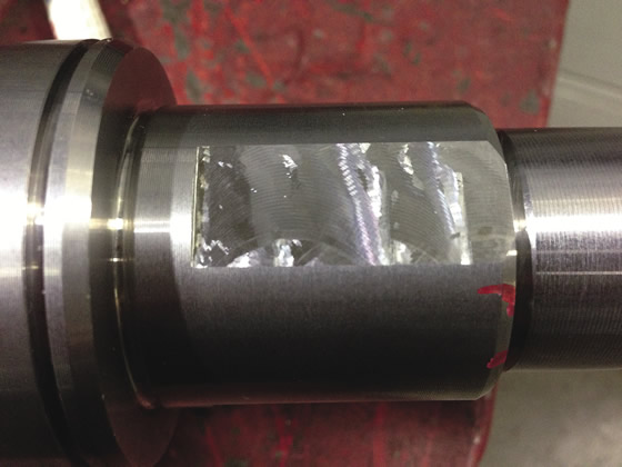
Machine Tool & Gear was imparting unacceptable surface finishes when milling flats.
Kischnick proposed replacing the milling tool with Horn’s Mini Mill, which is designed for facemilling and has a positive axial helix on all flutes, so the cutting forces are in one direction—downward. To further enhance rigidity, the Mini Mill’s steel holder eliminates the collet. “It has the shape of an ER20 collet on the back end, and the front end is actually the endmill holder all in one piece,” he explained.
Achieving the specified surface finish of 30 µin. Ra without an additional operation between the roughing and finishing passes required minimizing cutting pressure by reducing the number of teeth in the cut from six to three and leaving only 0.002 " (0.051mm) of material for the finishing pass. In addition, Kischnick employed a “trick” to relieve multidirectional tool pressure, which causes a tool to chatter and cut less freely. The trick is to move the tool “a few thousandths of an inch” from a flat’s sidewall during finishing.
“Any time you cut with the side and the bottom of a tool at the same time, you have opposing cutting forces against the tool: one at the bottom and one radially,” Kischnick said. “What I wanted was only to cut with the floor, or bottom, of the tool, and not have any of the sidewall hit the flutes, which makes the tool bounce.” That approach imparted a fine surface finish, he added.
After spending about 6 hours on the application, Kischnick noted the Mini Mill imparted a 15 to 20 µin. Ra surface finish. The final machining parameters are 715 sfm (217.932 m/min.) for roughing and finishing, a 0.058 " (1.473mm) DOC for roughing and a 0.002 " DOC for finishing, and a 0.004 " (0.107mm) ipt for roughing and a 0.002 " ipt for finishing. Because the previous tool could only achieve a surface finish of 80 to 100 µin. Ra, MG&T didn’t have any qualified speeds and feeds for producing the flats with that tool, he added.
“I was very impressed with Horn USA’s knowledge and how they took the time to help solve the problem,” MT&G’s Ochodnicky said. “As a result, we saved the expense of buying another machine tool and kept additional labor costs out of our process.”
Related Glossary Terms
- chatter
chatter
Condition of vibration involving the machine, workpiece and cutting tool. Once this condition arises, it is often self-sustaining until the problem is corrected. Chatter can be identified when lines or grooves appear at regular intervals in the workpiece. These lines or grooves are caused by the teeth of the cutter as they vibrate in and out of the workpiece and their spacing depends on the frequency of vibration.
- collet
collet
Flexible-sided device that secures a tool or workpiece. Similar in function to a chuck, but can accommodate only a narrow size range. Typically provides greater gripping force and precision than a chuck. See chuck.
- endmill
endmill
Milling cutter held by its shank that cuts on its periphery and, if so configured, on its free end. Takes a variety of shapes (single- and double-end, roughing, ballnose and cup-end) and sizes (stub, medium, long and extra-long). Also comes with differing numbers of flutes.
- facemilling
facemilling
Form of milling that produces a flat surface generally at right angles to the rotating axis of a cutter having teeth or inserts both on its periphery and on its end face.
- flat ( screw flat)
flat ( screw flat)
Flat surface machined into the shank of a cutting tool for enhanced holding of the tool.
- flutes
flutes
Grooves and spaces in the body of a tool that permit chip removal from, and cutting-fluid application to, the point of cut.
- gang cutting ( milling)
gang cutting ( milling)
Machining with several cutters mounted on a single arbor, generally for simultaneous cutting.
- inches per tooth ( ipt)
inches per tooth ( ipt)
Linear distance traveled by the cutter during the engagement of one tooth. Although the milling cutter is a multi-edge tool, it is the capacity of each individual cutting edge that sets the limit of the tool, defined as: ipt = ipm/number of effective teeth 5 rpm or ipt = ipr/number of effective teeth. Sometimes referred to as the chip load.
- machining center
machining center
CNC machine tool capable of drilling, reaming, tapping, milling and boring. Normally comes with an automatic toolchanger. See automatic toolchanger.
- milling
milling
Machining operation in which metal or other material is removed by applying power to a rotating cutter. In vertical milling, the cutting tool is mounted vertically on the spindle. In horizontal milling, the cutting tool is mounted horizontally, either directly on the spindle or on an arbor. Horizontal milling is further broken down into conventional milling, where the cutter rotates opposite the direction of feed, or “up” into the workpiece; and climb milling, where the cutter rotates in the direction of feed, or “down” into the workpiece. Milling operations include plane or surface milling, endmilling, facemilling, angle milling, form milling and profiling.
- milling machine ( mill)
milling machine ( mill)
Runs endmills and arbor-mounted milling cutters. Features include a head with a spindle that drives the cutters; a column, knee and table that provide motion in the three Cartesian axes; and a base that supports the components and houses the cutting-fluid pump and reservoir. The work is mounted on the table and fed into the rotating cutter or endmill to accomplish the milling steps; vertical milling machines also feed endmills into the work by means of a spindle-mounted quill. Models range from small manual machines to big bed-type and duplex mills. All take one of three basic forms: vertical, horizontal or convertible horizontal/vertical. Vertical machines may be knee-type (the table is mounted on a knee that can be elevated) or bed-type (the table is securely supported and only moves horizontally). In general, horizontal machines are bigger and more powerful, while vertical machines are lighter but more versatile and easier to set up and operate.
- toolholder
toolholder
Secures a cutting tool during a machining operation. Basic types include block, cartridge, chuck, collet, fixed, modular, quick-change and rotating.
Author

Alan holds a bachelor’s degree in journalism from Southern Illinois University Carbondale. Including his 20 years at CTE, Alan has more than 30 years of trade journalism experience.


