Shafts and tubes are straightened using the same flame straightening techniques used for plates. An easy way to straighten a shaft is in V-blocks or, better yet, mounted between centers in a lathe using piped coolant.
The severity of the bend determines what type of heat shrink to apply, with either an axial or a radial shrink used with shafts or other cylindrical parts. Excellent results can be achieved with this method. If you want to fuss around, you can easily get below 0.005 " runout.
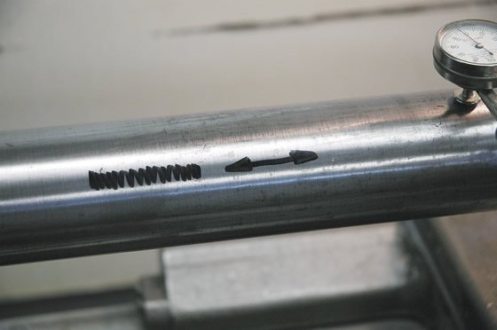
The axial shrink is a gentler heat straightening method for shafts and tubes than the radial shrink. All images courtesy T. Lipton.
The axial shrink is the gentler of the two, while the radial shrink is for heavy-duty distortion and should only be used if the axial shrink does not produce the desired result. With the axial shrink, the heat is applied in the same direction as the shaft length. Normally, these are short shrinks, because the high points on shafts are localized.
A dial indicator can be easier to use than a straightedge to accurately locate the high points on a shaft. These points are plotted and marked in the same way you would mark a flat plate. Because you mark the high spots, all of your indicator readings will be plus readings. I use the center of the plus as my target when applying the shrink.
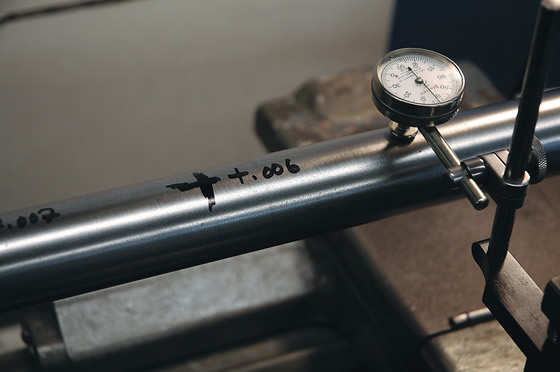
A dial indicator can be used more easily than a straightedge to accurately locate the high points on a shaft.
When you apply the axial heat shrink to the shaft, start a little before the high spot and continue the same amount beyond it. The maximum length for any axial heat shrink should be less than 2 ". If more shrinking is needed, a radial shrink should be applied.
For a radial shrink, the amount of shrinking is controlled by the radial distance that the shrink is carried around the circumference from the high spot of the distortion. When starting, shrink about 20° to 30° of the radial arc. If you don’t achieve the desired results, more and more arc length must be added, up to a maximum of about 120° of the arc. If this still is not enough, additional shrinks can be added alongside or with mechanical aids—such as clamps, weights and even gravity—to work a stubborn bend.
In addition, a special application of heat shrinking is worth mentioning. The high-aspect-ratio shrink is used for sections with a greater depth than width, like rectangular bar or beam sections. Section depth limits how much correction you can achieve from normal shrinking of the distortion apex. For these deep sections, you need to involve more of the material. Remember the rule of thumb: the shrink width is roughly equal to the thickness or, in this case, the depth of the material. For these types of parts, use a high-aspect-ratio, or V, shrink.
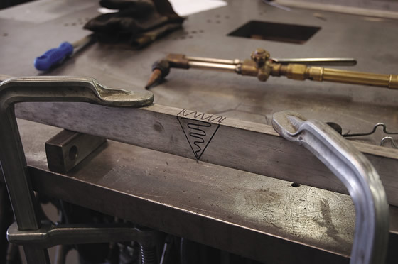
When performing a high-aspect-ratio shrink, draw two lines separated by a distance about equal to the depth of the section and then connect these lines to form a V.
First, draw two lines separated by a distance about equal to the depth of the section and then connect these lines to form a V. This is the material you will shrink to correct this type of section. The V points away from the high spot of the correction. Typically, both sides of the V are heated and shrunk.
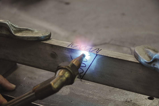
Start with the widest part and weave your way down to the point of the triangle when performing a high-aspect-ratio shrink.
When you heat this type of shrink, start with the widest part and weave your way down to the point of the triangle. Mechanical aids can greatly assist in these cases, allowing straightening that would otherwise be impossible. For example, you can use a spray bottle filled with water and a little soluble oil, similar to coolant used in a lathe, to cool the hottest part first.
The effective use of flame straightening can only be learned by trying it and carefully observing the results. The only real requirement is the willingness to try it. Flame straightening is not the answer to every distortion problem that a metal fabricator faces. It is simply another tool in the tool bag of a competent metalworker. The importance of good design and the use of proper manufacturing techniques are at least as important as knowing how to correct and repair defects. CTE
About the Author: Tom Lipton is a career metalworker who has worked at various job shops and lives in Alamo, Calif. Lipton’s column is adapted from information in his book “Metalworking Sink or Swim: Tips and Tricks for Machinists, Welders, and Fabricators,” published by Industrial Press Inc., South Norwalk, Conn. The publisher can be reached by calling (888) 528-7852 or visiting www.industrialpress.com. By indicating the code CTE-2015 when ordering, CTE readers will receive a 20 percent discount off the book’s list price of $44.95.
Related Glossary Terms
- centers
centers
Cone-shaped pins that support a workpiece by one or two ends during machining. The centers fit into holes drilled in the workpiece ends. Centers that turn with the workpiece are called “live” centers; those that do not are called “dead” centers.
- coolant
coolant
Fluid that reduces temperature buildup at the tool/workpiece interface during machining. Normally takes the form of a liquid such as soluble or chemical mixtures (semisynthetic, synthetic) but can be pressurized air or other gas. Because of water’s ability to absorb great quantities of heat, it is widely used as a coolant and vehicle for various cutting compounds, with the water-to-compound ratio varying with the machining task. See cutting fluid; semisynthetic cutting fluid; soluble-oil cutting fluid; synthetic cutting fluid.
- flat ( screw flat)
flat ( screw flat)
Flat surface machined into the shank of a cutting tool for enhanced holding of the tool.
- lathe
lathe
Turning machine capable of sawing, milling, grinding, gear-cutting, drilling, reaming, boring, threading, facing, chamfering, grooving, knurling, spinning, parting, necking, taper-cutting, and cam- and eccentric-cutting, as well as step- and straight-turning. Comes in a variety of forms, ranging from manual to semiautomatic to fully automatic, with major types being engine lathes, turning and contouring lathes, turret lathes and numerical-control lathes. The engine lathe consists of a headstock and spindle, tailstock, bed, carriage (complete with apron) and cross slides. Features include gear- (speed) and feed-selector levers, toolpost, compound rest, lead screw and reversing lead screw, threading dial and rapid-traverse lever. Special lathe types include through-the-spindle, camshaft and crankshaft, brake drum and rotor, spinning and gun-barrel machines. Toolroom and bench lathes are used for precision work; the former for tool-and-die work and similar tasks, the latter for small workpieces (instruments, watches), normally without a power feed. Models are typically designated according to their “swing,” or the largest-diameter workpiece that can be rotated; bed length, or the distance between centers; and horsepower generated. See turning machine.
Author

Tom Lipton is a career metalworker from the San Francisco Bay area who has worked at various job shops. For more information, visit his blog and YouTube video channel.


