Surprisingly, it’s not uncommon for machinists to feel like they’re starting at square one when setting up and running a repeat job. The primary reason is lack of documentation.
When a new job arrives, I first create a bill of operations, or process sheet. A BOO provides a road map for how to process a given part. The more complex the part, the more detailed the BOO should be. Some like to keep it short and sweet, but I prefer to be as descriptive as possible to reduce or eliminate the number of questions that come up later on.
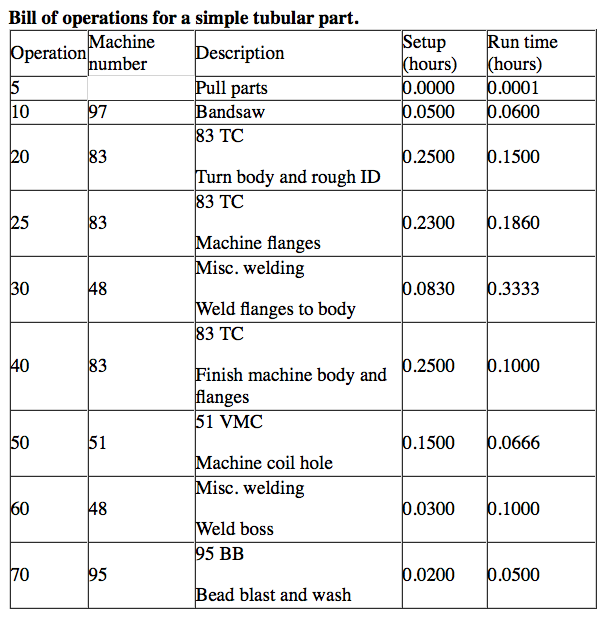
Note that the BOO shown here includes the operation number, machine number, work description, setup time and part run time. This enables you to access process information with a quick glance.
This BOO is for a simple tubular part, which is first cut to length on a bandsaw. Then it’s turned on a lathe before being welded. After welding, the workpiece returns to the lathe for finish turning, goes to a vertical machining center for holemaking and heads back to the welding department to weld on a boss. Bead blasting is the final operation.
Additional information on a BOO can prove helpful. For example, if the welds must be aesthetically pleasing, include an image of a good weld. A more complicated part typically includes a drawing with dimensions.
But what about the fixture and how to mount the part onto the fixture? Many shops fail to correctly document this on a BOO. I give the guys in the shop a drawing that shows the fixture and workpiece and provides the X, Y and Z coordinates from the tram hole on the fixture to the X and Y zero reference points of the part for all sides that require machining. I also provide images of the part loaded onto the fixture. If there is something I need to provide detail on, I document it with a close-up shot. Spending extra time up front to show the little things can save a lot of operating time down the line.
Relying on your memory can be effective for many activities, but not job setup. I can remember saying, “This setup is a piece of cake; it’s burned into my brain!” Then, the job repeats 6 weeks later and I have forgotten what fixture and tools I used. By documenting everything you do, you can probably reduce setup time 50 percent the next time that job comes around.
Sometimes, you just can’t document everything the first time because time runs out or you’re not there when the part is run, but document as much as you can. The next time that job comes in, document more of it. By the third go-round, your documentation should be up to snuff. When that job repeats, you’ll feel confident that the job packet you hand the machinist has everything he needs to run the job successfully.
Related Glossary Terms
- bandsaw
bandsaw
Machine that utilizes an endless band, normally with serrated teeth, for cutoff or contour sawing. See saw, sawing machine.
- fixture
fixture
Device, often made in-house, that holds a specific workpiece. See jig; modular fixturing.
- lathe
lathe
Turning machine capable of sawing, milling, grinding, gear-cutting, drilling, reaming, boring, threading, facing, chamfering, grooving, knurling, spinning, parting, necking, taper-cutting, and cam- and eccentric-cutting, as well as step- and straight-turning. Comes in a variety of forms, ranging from manual to semiautomatic to fully automatic, with major types being engine lathes, turning and contouring lathes, turret lathes and numerical-control lathes. The engine lathe consists of a headstock and spindle, tailstock, bed, carriage (complete with apron) and cross slides. Features include gear- (speed) and feed-selector levers, toolpost, compound rest, lead screw and reversing lead screw, threading dial and rapid-traverse lever. Special lathe types include through-the-spindle, camshaft and crankshaft, brake drum and rotor, spinning and gun-barrel machines. Toolroom and bench lathes are used for precision work; the former for tool-and-die work and similar tasks, the latter for small workpieces (instruments, watches), normally without a power feed. Models are typically designated according to their “swing,” or the largest-diameter workpiece that can be rotated; bed length, or the distance between centers; and horsepower generated. See turning machine.
- machining center
machining center
CNC machine tool capable of drilling, reaming, tapping, milling and boring. Normally comes with an automatic toolchanger. See automatic toolchanger.
- turning
turning
Workpiece is held in a chuck, mounted on a face plate or secured between centers and rotated while a cutting tool, normally a single-point tool, is fed into it along its periphery or across its end or face. Takes the form of straight turning (cutting along the periphery of the workpiece); taper turning (creating a taper); step turning (turning different-size diameters on the same work); chamfering (beveling an edge or shoulder); facing (cutting on an end); turning threads (usually external but can be internal); roughing (high-volume metal removal); and finishing (final light cuts). Performed on lathes, turning centers, chucking machines, automatic screw machines and similar machines.
Author

Michael Deren is a manufacturing engineer/project manager and a regular CTE contributor. He can be reached via e-mail at [email protected].


