Process monitors—either vibration- or digitally based—help parts manufacturers save money and ensure quality on small production runs.
Shop Supervisor Jacek Janasek said he’ll think twice before milling, drilling or turning even 50 metal parts without a process monitor.
The origin of Janasek’s resolve dates to last September, when his employer, Duratrack Inc., Elk Grove Village, Ill., installed ATAM 6000-PC process monitors on two CNC lathes. The goals were to ensure consistent quality and allow unattended operation of the machines on more jobs.
All images: ATAM Systems
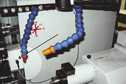
The ATAM System’s sensors are designed to alert operators or shut down equipment when machine vibrations exceed preset parameters.
While Janasek knew all about the monitors’ benefits, what happened the day after their installation, when they weren’t running, made him a true believer in the technology.
Duratrak had received an order for 50 intricate eye bolts, each with a groove and outside profile, to be used for curtain hardware applications. Like much of the company’s work, which usually involves 50- to 200-part runs, the job was a repeat order. Janasek and his workers had done it countless times and felt they had a good handle on the part’s program. Did they really need to use the new process monitor for the job?
Janasek conferred with his CNC operator. “We wanted to save that 15 minutes [needed to program the monitor], so we decided, ‘let’s just run those 50 pieces and be done with it, then we will start putting the ATAM into effect on the higher quantity jobs.’ ”
That’s exactly the point in the story where Janasek today wishes he could turn back the clock. Shortly into the job, “We wiped out the carbide insert and shim of the 35° profiling tool; we also damaged the grooving tool and part of the toolholder. Because the cutter kept running, about 15 parts ended in the scrap hopper. After all that, we said, ‘OK, we’re not going to run a job like that again without monitoring it unless there’s a very compelling reason—like the ATAM is broken. And that’s that.”
Wide Benefits
Sensor-based monitors, such as the one from ATAM, track machining operations and compare each procedure to an input signature of a programmed cycle run. Any deviation from the signature cycle can activate an alarm or prompt a shutdown, thereby averting a crash. The advantages are many: controlling quality, reducing waste, protecting against tool and parts damage and allowing lights-out manufacturing.
Often used for high-volume and expensive part runs, the benefits of process monitoring also extend to the smaller runs typically tackled by job shops.
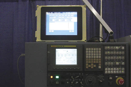
The ATAM displays machining operations and tool condition on a monitor in the form of a graph-like scrolling signature.
“We define short runs as either repeatable small-quantity jobs or those with one type of part that you will never see again,” said Harry Kincaid, owner and president of ATAM Systems Inc., New Albany, Ohio.
In either case, proper monitoring can be a big money saver. “If you’re doing a lot of different setups for different parts, your chances of making a mistake—overlooking a little detail, for instance—increase exponentially,” Kincaid said. “If you don’t have crash protection on your machine, your money-making device can be put out of commission.”
He added that the protection afforded by monitoring also allows shops to step up production. “You can reduce your cycle and air cutting time from the operations,” Kincaid said. “People tend to drop out of rapid with their tool way too soon when coming to the part, because they’re afraid of something crashing or breaking. But with the monitor’s protection, you can be much bolder and reduce your noncutting air time.” If for any reason the tool begins to function contrary to preset parameters, he added, within a millisecond the monitor can either deliver a warning or safely stop the machine.
Shops focused on small runs often opt against process monitors because the technology entails yet another setup operation, procedures that already consume a sizable portion of their workday, Kincaid said. Also, because such orders might be a one-time job, shops don’t see the advantage process monitors would provide. These companies will resort to conducting all machining operations very conservatively and slowly. And that’s a valid strategy, given that “they are running unprotected,” Kincaid said. “But the protection provided by process monitors would afford those shops the opportunity for greater productivity.”
Kincaid added that if a shop is using an off-machine setup software package, inserting tool call commands for the ATAM “takes only seconds to add to the part program. Some software packages can even add the commands automatically.”
The ATAM incorporates a computer-based control and sensors. The unit connects to the machine’s controller and its sensors are placed on the machine. Using vibration as its primary criterion, the ATAM’s report on tool condition is displayed on a monitor in the form of a graph-like scrolling signature. (ATAM Systems offers two types of process monitors: the ATAM 6000, which includes an interactive touch-screen; and the ATAM 6000-PC, which includes all of the 6000 features, but shops substitute their own PC in place of the interactive touch screen.)
The system alerts operators when preset machining parameters are exceeded. Slightly elevated vibration levels due to a tool beginning to wear, for example, might prompt a warning, in which case the machine would stop at the end of a cycle. Vibration levels beyond a chosen crash limit would shut down the machine.
“Seventy to 80 percent of our sensor input comes from vibration,” Kincaid said. “The rest of the input comes from either power or strain force. The ATAM has a unique filter window and very fast signal processing. We can control that processing function to match the situation we face on a machine.”
Duratrack purchased two types of ATAM monitoring sensors, Janasek said. The company uses vibration sensors for conventional turning and amperage sensors for live tooling operations.
While Janasek has yet to quantify exactly how much ATAM system has helped Duratrack reduce waste or minimize tool damage, he has seen benefits. “It used to be that whenever we would set up a new job, we would rotate the insert or put a new insert in the new edge,” he said. “But now we can leave in the insert from the previous job and let it fly. So our setups are quicker because we have decreased need for new tools.”
He also said the system has eliminated the need for operators to check parts every half hour or make sure the machine hasn’t crashed. The time savings for operators was a key consideration in Duratrack’s decision to opt for an ATAM system.
In addition, Janasek said, “I researched the [process monitoring] field and ATAM was the most appealing because its software is extremely easy to use. That’s important because you do want to be able to cross train. So you want something that’s reliable and easy to operate.”
Digital Design
Eight months ago, Northrop Grumman Corp., El Segundo, Calif., opted for a digitally based process monitor for drilling from Artis Systems Inc., Livonia, Mich. (Artis has since been acquired by inspection equipment manufacturer Marposs Corp., Auburn Hills, Mich.)
The application involves monitoring cutter wear when drilling about 750 holes on each side of an F-18 airplane’s vertical stabilizer. Northrop produces two stabilizers a week. “We have a complex stackup of various materials [in the stabilizer], so even the same hole in different units can have different profiles,” said Omid Mohseni, manufacturing engineer for Northrop Grumman.
The operation’s complexity, joined with the high-priced part, prompted Northrop to automate process monitoring. “We had a few issues in the past when we had a broken cutter, which the operator was not able to catch in time and it created subsequent defects [in the part],” said Mohseni.
Artis’ dx/dt process monitor, he continued, “is a system that’s always on, but runs unobtrusively and passively in the background.” By monitoring spindle torque, the dx/dt can precisely measure cutter action and determine whether a cutter is becoming dull, is broken or missing.
“Essentially, all the data comes from the spindle torque,” Mohseni said. “The software analyzes that data and, depending on the parameters you give it, decides whether to let the machine continue to drill or stop altogether.”
Introduced in 2004, the dx/dt is an optional function within Artis’ CTM (Computer Integrated Tool and Machine Monitoring) package, said John Maher, Artis’ director of business development, North America. “From an in-process monitoring standpoint, we offer two strategies.” The CTM plugs into an open peripheral component interconnect slot on a machine’s control. The basic CTM package, used for short or long runs, can monitor up to 65,000 different processes, and does so by comparing an in-process operation against preset parameters.
“We can record the known, good values for a procedure by measuring the horsepower or digital torque information direct from the servodrives,” Maher said. “With that we can do comparisons [with subsequent jobs], and if there’s an aberration in the horsepower or digital signals, we can flag the control and stop the machine.”
The CTM’s dx/dt option, he added, is a solution when machining short runs or single workpieces. As such, it doesn’t depend on comparative data; and because parameters can be programmed offline, downtime is minimal.
The dx/dt provides both dynamic and static monitoring. In its dynamic function, it tracks digital torque data for fast, positive or negative signal changes, or spikes. Whereas positive spikes would indicate brief increases in force and, possibly, tool breakages, negative spikes appear, for example, when carbide tool cutting edges break.
In its static mode, dx/dt monitors for absolute maximum values, or thresholds, for wear, breakage, overload or a missing tool.
Artis’ Adaptive Control (feed rate override), an optional feature that can be used with dx/dt, can automatically speedup or slowdown a machine’s feed rate based on the spindle torque values. “Upper and lower feed rate limits can be individually adjusted by the end user,” Maher said. “Certainly in military or aerospace applications, they have a certain specification of feeds and speeds, and we can work within those ranges they give us to make sure the machine override feed rate works accordingly. And that’s basically to ensure quality control of the part.”
At Northrop Grumman, where monitoring parameters included averting ruined parts from undetected tool damage, the dx/dt has proven its value. “It’s caught a few broken cutters midprocess and flagged the operators,” Mohseni said. “So it is working just as advertised.” CTE
About the Author: Daniel McCann is senior editor of Cutting Tool Engineering. He can be reached at [email protected] or (847) 714-0177.
Contributors
Artis Systems Inc.
(734) 779-1665
www.artis-systems.com
ATAM Systems Inc.
(614) 939-2266
www.atam.com
Duratrack Inc.
(847) 806-0202
www.duratrack.com
Marposs Corp.
(248) 370-0404
www.marposs.com
Northrop Grumman Corp.
(310) 332-1000
www.northropgrumman.com
Spawr Industries Inc.
(928) 453-8800
www.spawrindustries.com
Process monitoring for laser welding
As manufacturing technology diversifies, so must the methods used to monitor it. The growing use of lasers, for instance, has spawned novel process monitoring systems. Ten years ago, Spawr Industries Inc., Lake Havasu City, Ariz., and Argonne (Ill.) National Laboratory jointly developed a process monitor for laser welding applications.
Shaped like a small coffee-table book and equipped with an optics lens, the device focuses on infrared light. “If you’re welding something, the weld pool emits a particular spectral emission,” said Walter Spawr, president and founder of Spawr Industries and co-inventor of the Spawr laser process monitor.
The monitor’s optic lens includes a photovoltaic detector that reacts to the weld’s infrared light and produces an electrical signal. Computer software then analyzes the signal and provides a graphical representation “that tells you the quality of that [laser welding] process,” said Spawr.
Whereas other monitors gauge weld quality based on weld topography and size, the Spawr monitor focuses on the source of the radiation, and thus can provide a picture reference of the morphology inside the weld in real time.
“What we have found is that when there is a variation of the penetration depth or size of the pool, then the amplitude of the emission changes,” said Spawr. “For instance, if you’re processing a piece of material that is a ¼ " thick and your weld penetration is about ¼ ", you can actually detect variations of that penetration on the order of 0.005".”
The Spawr monitor can detect blowholes, discontinuities and changes in the consistency of the materials, i.e., welds with different alloys produce different signature profiles. The monitor provides the same accuracies when used for real-time heat treating penetration depth and hardness qualification.
—D. McCann
MIDA product line targets all phases
With its December acquisition of Artis Systems Inc., Marposs Corp. aims to provide shops with a full complement of pre-, post- and in-process monitoring and inspection tools, said Gary Sicheneder, Marposs’ manager of new business development and marketing.
“When you talk about series production, onesies or twosies, Marposs offers a product line of tool, part probing and monitoring systems called MIDA,” Sicheneder said. “And whether it’s a machining center, mill or lathe, we offer a range of capabilities—from verifying tool size and fixture location to on-machine 3-D shape inspection of the part.”
Additionally, Marposs’ MIDA product line for tool and process monitoring includes:
• a vibration monitor to detect unbalanced tool movements, spindle collision and bearing damage;
• a power monitor for detecting wear and damage during grinding, tapping, turning, drilling and milling;
• a force monitor to identify excessive strains on tools;
• a displacement monitor used to measure distances and high-resolution displacement; and
• a temperature monitor for use inside spindles and to detect variations on X, Y and Z axes.
“In addition,” Sicheneder said, “after or during the machining, we can inspect the part with our 3DSI (Shape Inspector) technology. With this we can load software into the machine’s controller and verify the condition of the part before it’s taken out of the fixture.
“So you can actually machine it up to a certain point, stop and check on a virtually unlimited number [of data] before going on to the next stage, which is probably the finishing step, in the same machine,” he said.
—D. McCann
Related Glossary Terms
- 3-D
3-D
Way of displaying real-world objects in a natural way by showing depth, height and width. This system uses the X, Y and Z axes.
- alloys
alloys
Substances having metallic properties and being composed of two or more chemical elements of which at least one is a metal.
- computer numerical control ( CNC)
computer numerical control ( CNC)
Microprocessor-based controller dedicated to a machine tool that permits the creation or modification of parts. Programmed numerical control activates the machine’s servos and spindle drives and controls the various machining operations. See DNC, direct numerical control; NC, numerical control.
- feed
feed
Rate of change of position of the tool as a whole, relative to the workpiece while cutting.
- fixture
fixture
Device, often made in-house, that holds a specific workpiece. See jig; modular fixturing.
- gang cutting ( milling)
gang cutting ( milling)
Machining with several cutters mounted on a single arbor, generally for simultaneous cutting.
- grinding
grinding
Machining operation in which material is removed from the workpiece by a powered abrasive wheel, stone, belt, paste, sheet, compound, slurry, etc. Takes various forms: surface grinding (creates flat and/or squared surfaces); cylindrical grinding (for external cylindrical and tapered shapes, fillets, undercuts, etc.); centerless grinding; chamfering; thread and form grinding; tool and cutter grinding; offhand grinding; lapping and polishing (grinding with extremely fine grits to create ultrasmooth surfaces); honing; and disc grinding.
- grooving
grooving
Machining grooves and shallow channels. Example: grooving ball-bearing raceways. Typically performed by tools that are capable of light cuts at high feed rates. Imparts high-quality finish.
- hardness
hardness
Hardness is a measure of the resistance of a material to surface indentation or abrasion. There is no absolute scale for hardness. In order to express hardness quantitatively, each type of test has its own scale, which defines hardness. Indentation hardness obtained through static methods is measured by Brinell, Rockwell, Vickers and Knoop tests. Hardness without indentation is measured by a dynamic method, known as the Scleroscope test.
- lathe
lathe
Turning machine capable of sawing, milling, grinding, gear-cutting, drilling, reaming, boring, threading, facing, chamfering, grooving, knurling, spinning, parting, necking, taper-cutting, and cam- and eccentric-cutting, as well as step- and straight-turning. Comes in a variety of forms, ranging from manual to semiautomatic to fully automatic, with major types being engine lathes, turning and contouring lathes, turret lathes and numerical-control lathes. The engine lathe consists of a headstock and spindle, tailstock, bed, carriage (complete with apron) and cross slides. Features include gear- (speed) and feed-selector levers, toolpost, compound rest, lead screw and reversing lead screw, threading dial and rapid-traverse lever. Special lathe types include through-the-spindle, camshaft and crankshaft, brake drum and rotor, spinning and gun-barrel machines. Toolroom and bench lathes are used for precision work; the former for tool-and-die work and similar tasks, the latter for small workpieces (instruments, watches), normally without a power feed. Models are typically designated according to their “swing,” or the largest-diameter workpiece that can be rotated; bed length, or the distance between centers; and horsepower generated. See turning machine.
- machining center
machining center
CNC machine tool capable of drilling, reaming, tapping, milling and boring. Normally comes with an automatic toolchanger. See automatic toolchanger.
- milling
milling
Machining operation in which metal or other material is removed by applying power to a rotating cutter. In vertical milling, the cutting tool is mounted vertically on the spindle. In horizontal milling, the cutting tool is mounted horizontally, either directly on the spindle or on an arbor. Horizontal milling is further broken down into conventional milling, where the cutter rotates opposite the direction of feed, or “up” into the workpiece; and climb milling, where the cutter rotates in the direction of feed, or “down” into the workpiece. Milling operations include plane or surface milling, endmilling, facemilling, angle milling, form milling and profiling.
- milling machine ( mill)
milling machine ( mill)
Runs endmills and arbor-mounted milling cutters. Features include a head with a spindle that drives the cutters; a column, knee and table that provide motion in the three Cartesian axes; and a base that supports the components and houses the cutting-fluid pump and reservoir. The work is mounted on the table and fed into the rotating cutter or endmill to accomplish the milling steps; vertical milling machines also feed endmills into the work by means of a spindle-mounted quill. Models range from small manual machines to big bed-type and duplex mills. All take one of three basic forms: vertical, horizontal or convertible horizontal/vertical. Vertical machines may be knee-type (the table is mounted on a knee that can be elevated) or bed-type (the table is securely supported and only moves horizontally). In general, horizontal machines are bigger and more powerful, while vertical machines are lighter but more versatile and easier to set up and operate.
- profiling
profiling
Machining vertical edges of workpieces having irregular contours; normally performed with an endmill in a vertical spindle on a milling machine or with a profiler, following a pattern. See mill, milling machine.
- quality assurance ( quality control)
quality assurance ( quality control)
Terms denoting a formal program for monitoring product quality. The denotations are the same, but QC typically connotes a more traditional postmachining inspection system, while QA implies a more comprehensive approach, with emphasis on “total quality,” broad quality principles, statistical process control and other statistical methods.
- tapping
tapping
Machining operation in which a tap, with teeth on its periphery, cuts internal threads in a predrilled hole having a smaller diameter than the tap diameter. Threads are formed by a combined rotary and axial-relative motion between tap and workpiece. See tap.
- toolholder
toolholder
Secures a cutting tool during a machining operation. Basic types include block, cartridge, chuck, collet, fixed, modular, quick-change and rotating.
- turning
turning
Workpiece is held in a chuck, mounted on a face plate or secured between centers and rotated while a cutting tool, normally a single-point tool, is fed into it along its periphery or across its end or face. Takes the form of straight turning (cutting along the periphery of the workpiece); taper turning (creating a taper); step turning (turning different-size diameters on the same work); chamfering (beveling an edge or shoulder); facing (cutting on an end); turning threads (usually external but can be internal); roughing (high-volume metal removal); and finishing (final light cuts). Performed on lathes, turning centers, chucking machines, automatic screw machines and similar machines.


